 English
 русский
 Español
 عربى
عربى
JingShi
JingShi
JingShi
JingShi
JingShi
JingShi
JingShi
JingShi
JingShi
Content
- 1 What Are Vacuum System Components?
- 2 The 6 Core Components of a Vacuum System
- 3 How to Select the Right Vacuum Generator: Electric vs. Pneumatic
- 4 Filters and Connectors: Protecting Your System from Contamination
- 5 Common Vacuum System Failures and How to Troubleshoot Them
- 6 Vacuum Component Selection Matrix: Matching Parts to Your Application
What Are Vacuum System Components?
Every automated handling system that relies on vacuum shares a delicate balance. The right combination of components can mean the difference between reliable production and constant downtime. Yet too many engineers treat these parts as isolated purchases instead of as a single, coordinated system.
Vacuum system components are the functional building blocks that generate, distribute, control, and monitor vacuum to grip, move, and release workpieces. They work in concert, not in isolation. A suction cup without proper filtration will fail prematurely. A generator oversized for its plumbing wastes energy. Understanding how these modules interact is the first step toward a robust, low-maintenance setup.
The industry typically groups vacuum system components into six functional modules:
- Gripping elements – suction cups and special grippers that contact the workpiece
- Vacuum generation – ejectors, pumps, or blowers that create the required negative pressure
- System monitoring – switches, sensors, and gauges that track vacuum level and signal faults
- Filtration – elements that protect the generator and valves from dust, moisture, and debris
- Connectors – hoses, fittings, flanges, and mounting elements that link components into a sealed circuit
- Control and valving – directional valves, check valves, and release valves that regulate flow
In the sections that follow, we’ll walk through each module, highlight critical selection criteria, and provide the decision-making frameworks that commercial buyers need to specify components confidently.
The 6 Core Components of a Vacuum System
No single component carries a vacuum system. Each module has a specific job, and mismatching any one of them erodes performance across the entire circuit. The overview below breaks down what each module does, the common variants available, and the primary selection considerations that impact cost and reliability.
1. Vacuum Suction Cups and Special Grippers
Suction cups are the interface between the system and the workpiece. A cup that loses grip under load—or wears out after a few thousand cycles—can halt an entire production line. The shape, diameter, and material of the cup must be matched to the surface finish, temperature, and weight of the object being handled.
Common suction cup shapes include flat cups for smooth surfaces, bellows cups for contoured or flexible parts, and oval cups for narrow profiles. Material selection is equally critical. A nitrile (NBR) cup performs well on oily metal sheets but degrades quickly at elevated temperatures. Silicone withstands high heat and leaves no marks, making it ideal for glass or painted surfaces. Polyurethane offers superior abrasion resistance on rough materials like wood or cardboard.
The table below summarizes suction cup material choices against typical working conditions. Use it as a starting reference during specification.
| Material | Surface Condition | Temperature Range | Typical Applications |
|---|---|---|---|
| NBR | Smooth, oily | -30 to 100 degrees C | Metal stamping, automotive panels |
| Silicone | Smooth, dry, delicate | -60 to 200 degrees C | Glass, electronics, food packaging |
| Polyurethane (PU) | Rough, abrasive | -20 to 60 degrees C | Cardboard, wood, textured plastics |
| Fluoroelastomer (FKM) | Chemical exposure | -10 to 200 degrees C | Semiconductor, chemical industry |
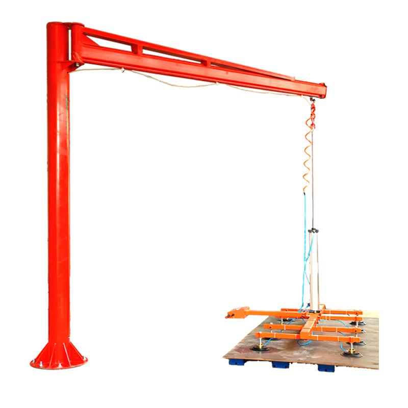
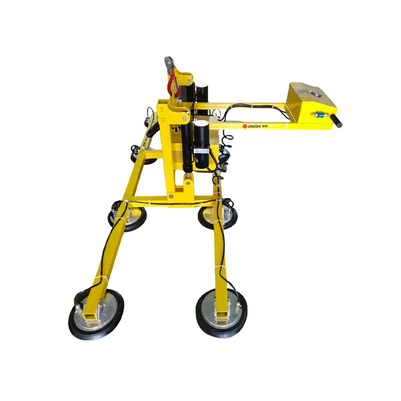
For heavy sheet metal or glass handling, a dedicated fixed suction cup lifting machine integrates the entire gripping and vacuum generation chain, eliminating the guesswork of matching individual components.
2. Vacuum Generators
Generators are the heart of the system. They create the pressure differential that holds the workpiece. The two dominant technologies are pneumatic ejectors (Venturi-based) and electric vacuum pumps or blowers. Ejectors are compact, inexpensive, and offer rapid response, making them common in decentralized gripping and high-speed pick‑and‑place. Electric pumps deliver higher flow rates and are more energy‑efficient in continuous operation, but they come with a larger footprint and higher upfront cost.
The choice hinges on duty cycle, available compressed air, and noise constraints. We’ll compare these trade‑offs in detail in the next section.
3. System Monitoring Devices
Monitoring components include vacuum switches, analog pressure transmitters, and digital gauges. They ensure that the vacuum level stays within the safe operating window. A simple mechanical switch may be enough for a single gripper, while a multi‑head system demands analog or IO‑Link sensors that can report per‑cup status. The key parameter is the setpoint resolution—narrow‑window detection prevents false alarms while still catching a leaking cup before the part drops.
4. Filters and Connectors
Filters prevent dust, oil mist, and process debris from entering the generator or clogging valves. They are installed on the suction side (vacuum filter), on the compressed air supply (air filter), and sometimes on the exhaust. The micron rating should match the generator’s tolerance; a 40‑micron screen is adequate for most pneumatic ejectors, while high‑precision electric pumps may require 5‑micron filtration. Connectors—hoses, push‑in fittings, and flanges—must provide sufficient conductance to avoid throttling the pump’s effective flow rate.
5. Valve Technology
Valves control when vacuum is applied, held, or released. Direct‑acting solenoid valves are fast and reliable for small circuits. Pilot‑operated valves handle larger flow capacities. A blow‑off (release) valve speeds up part separation, especially with flexible materials that tend to cling. Some systems incorporate check valves to maintain vacuum if the pump is interrupted, which is essential for handling fragile loads.
6. Mounting Elements and Structural Integration
Mounting brackets, spring‑loaded adapters, and level compensators ensure the cup makes contact at the right angle and pressure. These mechanical components are often overlooked, yet they directly affect cup wear and grip reliability. A badly aligned mounting element can double the replacement rate of suction cups and cause inconsistent pick results.
How to Select the Right Vacuum Generator: Electric vs. Pneumatic
Choosing between an electric vacuum pump and a pneumatic ejector isn’t just a question of technology preference. It shapes energy consumption, cycle time, and maintenance schedules. The wrong decision here ties up capital and drives up operating costs.
Pneumatic ejectors generate vacuum by accelerating compressed air through a Venturi nozzle. They have no moving parts, respond in milliseconds, and can be mounted directly at the point of use. This makes them ideal for applications with short cycle times and frequent on‑off cycling. However, they require a compressed air supply and are inherently less efficient: for every unit of vacuum power delivered, they consume several units of compressed air energy.
Electric pumps—rotary vane, claw, or screw types—produce vacuum through mechanical displacement. They deliver a steady flow at a lower specific energy cost and generate far less noise. An electric pump is often the right answer when vacuum is needed continuously for more than 30% of the cycle, or when compressed air availability is limited. The trade‑off is higher initial investment and larger physical dimensions.
| Criterion | Pneumatic Ejector | Electric Pump |
|---|---|---|
| Upfront cost | Low | Medium to high |
| Energy efficiency at 100% duty | Poor | Good |
| Response time | Very fast (milliseconds) | Moderate (seconds) |
| Noise level | High (70–85 dBA) | Low (55–65 dBA) |
| Maintenance requirement | Minimal (no moving parts) | Higher (filter changes, vane replacement) |
| Best application | High‑speed pick‑and‑place, decentralized gripping | Continuous holding, multi‑cup central systems |
When cycle times are below 2 seconds and the plant already has a robust compressed air infrastructure, pneumatic ejectors win on responsiveness and simplicity. For longer hold times, heavy parts, or central vacuum networks, electric pumps deliver clear long‑term savings.
Filters and Connectors: Protecting Your System from Contamination
Dirt is the silent killer of vacuum components. A single pinch of metal dust can score a pump’s internal rotors or block a tiny ejector nozzle. The role of filtration is not optional—it is an insurance policy built into the system from day one.
There are three critical filter locations. The vacuum‑side filter sits between the suction cup and the generator, catching debris drawn in from the workpiece. The compressed‑air filter (for pneumatic systems) removes oil, water, and scale from the supply before it reaches the ejector nozzle. An exhaust filter traps oil mist and reduces noise in pumps that vent to the room.
Filter element replacement intervals depend on the particle load. In a clean electronics assembly environment, a 5‑micron vacuum filter may last 6 months. In a foundry or woodworking shop, the same filter may clog in a week. A practical rule: monitor the pressure drop across the filter. When the differential exceeds the manufacturer’s limit, replace the element immediately—not during the next scheduled downtime.
Connectors complete the circuit. Undersized tubing creates a conductance bottleneck that starves the generator, regardless of its rated capacity. A basic guideline: for ejectors with a nozzle diameter up to 2 mm, use 6 mm or 8 mm OD tubing; for electric pumps above 10 m3/h, switch to reinforced hose of at least 12–16 mm ID. Standardized flange systems like ISO‑KF (small flanges for vacuum) provide reliable, leak‑free connections that can be disassembled without special tools. In high‑vacuum systems, CF (ConFlat) flanges with metal gaskets achieve leak rates below 1×10^-9 mbar·L/s. For most industrial handling applications, however, well‑specified push‑in fittings and polyurethane tubing deliver sufficient sealing performance at a fraction of the cost.
Common Vacuum System Failures and How to Troubleshoot Them
When a vacuum system underperforms, replacing components at random is expensive and ineffective. A structured troubleshooting process pinpoints the root cause in minutes. The table below maps the three most frequent failure symptoms to their likely causes, simple tests, and corrective actions.
| Symptom | Possible Cause | Quick Check | Solution |
|---|---|---|---|
| Insufficient holding force / part drops | Worn or cracked suction cup; leak in hose or fitting | Apply soapy water along connections while system is under vacuum; inspect cup edge for cuts | Replace cup; tighten or replace leaking connector |
| Slow vacuum build‑up | Clogged filter; undersized tubing; generator nozzle blockage | Measure pressure drop across filter; disconnect cup and check generator’s free flow | Replace filter element; upgrade to larger diameter hose; clean or replace nozzle |
| Abnormal noise | Exhaust silencer clogged; cavitation in pump; loose mounting | Remove silencer temporarily; check pump oil level and condition | Replace silencer; top‑up or change pump oil; tighten vibration isolators |
Suction cup wear is the number one reason for grip failure. Even a 1 mm crack along the sealing lip can drop a part. Establishing a visual inspection routine at shift start, combined with a pressure decay test via a vacuum switch, catches degradation before it causes production rejects. Similarly, valves that stick open or closed often respond to a quick cleaning of the spool; if the problem recurs, examine the compressed air quality upstream.
System monitoring devices pay for themselves here. An analog vacuum sensor with a teachable window can alert operators the moment the vacuum level drops below the safe threshold, turning a reactive maintenance culture into a predictive one.
Vacuum Component Selection Matrix: Matching Parts to Your Application
Specifying components shouldn’t start from a catalog page. It should start from the application’s physical demands: workpiece weight, surface texture, ambient conditions, and cycle rate. The following matrix provides a direct, practical map from those inputs to the recommended component categories.
| Application Profile | Recommended Suction Cup Type | Generator | Filtration | Valve Control |
|---|---|---|---|---|
| Light parts (<2 kg), smooth and dry, 60+ cycles/min | Small flat NBR, bellows optional | Single‑stage pneumatic ejector, decentralized | 40‑micron vacuum filter, basic air filter | Direct‑acting solenoid, fast blow‑off |
| Medium sheet metal (<30 kg), oily, 20 cycles/min | Large flat NBR or oval, spring‑loaded | Multi‑stage ejector or small electric pump | 5‑micron air filter with oil separator, 40‑micron vacuum filter | Pilot‑operated valve, check valve for safe hold |
| Heavy glass or panels (>30 kg), delicate surface | Oversized silicone bellows, level‑compensating | Electric claw pump, central vacuum supply | 5‑micron vacuum filter, high‑capacity exhaust filter | Soft‑start valve, controlled blow‑off release |
| Rough cardboard/wood, dusty environment | Polyurethane bellows, deep‑stroke | Multi‑stage ejector or blower | Coarse pre‑filter (100‑micron) plus 40‑micron vacuum filter | Fast direct‑acting valve with silencer |
In a full vacuum lifter system, these individual selections come pre‑integrated and tested, saving engineering time. For custom applications, this matrix provides a first‑pass configuration that you can refine with actual measured loads and ambient conditions.
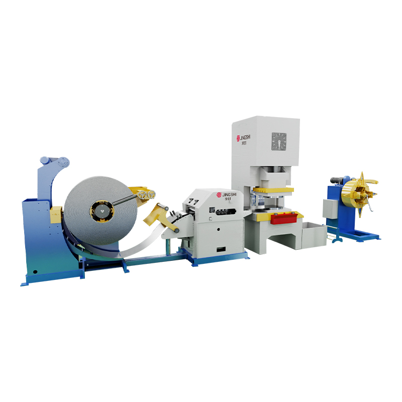
When the application involves handling coiled material or sheet blanks, the vacuum system often operates directly after a leveling or blanking line. For high‑volume steel processing, linking your vacuum components to a high‑precision decoiler straightener feeder CTL line ensures that the part arrives flat, clean, and ready for reliable pickup. This kind of end‑to‑end integration reduces part damage and extends component life across the entire workcell.