 English
 русский
 Español
 عربى
عربى
JingShi
JingShi
JingShi
JingShi
JingShi
JingShi
JingShi
JingShi
JingShi
Vacuum Lifter Manufacturers
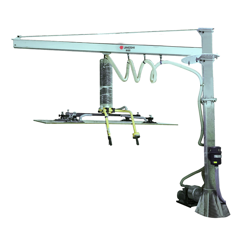

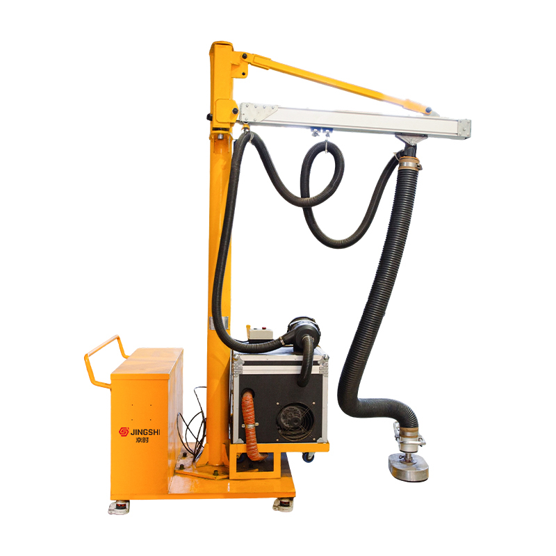
A vacuum lifter is a device that uses the principle of vacuum adsorption to transport materials and is widely used in industrial fields. Its core components consist of a vacuum pump, suction cups, vacuum piping, and a control system. The vacuum pump extracts air between the suction cups and the object's surface, creating a negative pressure adsorption force, thereby stably gripping flat workpieces such as glass, metal plates, and stone. It features high efficiency, safety, and non-destructive operation; it can quickly adsorb materials without traditional clamps, reducing material damage; it is easy to operate, with lifting and movement controlled via a handle or remote control, reducing manual labor intensity; the adsorption force is stable, and a vacuum monitoring system ensures safe and reliable handling.
Vacuum lifters can be categorized by application scenario into fixed, mobile (e.g., when used with a crane), and portable types, suitable for industries such as glass processing, automobile manufacturing, and warehousing and logistics. It is important to note that the surface of the object to be handled must be flat and sealed, and the airtightness of the vacuum system must be checked regularly.
About Us
Suzhou JingShi Intelligent Equipment Co., Ltd.
Founded in 2016 and headquartered in Suzhou, China, Suzhou JingShi Intelligent Equipment Co., Ltd. is an integrated high-tech enterprise combining research, manufacturing, and trade. We specialize in hydraulic precision leveling machines and intelligent production line systems, Custom Vacuum Lifter, committed to delivering high-precision, high-efficiency, and high-stability sheet-metal finishing solutions to global manufacturers.
As Vacuum Lifter Manufacturers and Vacuum Lifting Equipment Suppliers in China, our equipment is widely used in automotive parts, precision sheet metal, elevator components, agricultural machinery, saw blades, precision stamping, profile manufacturing, and electrical applications. Through continuous innovation and technical excellence, JingShi has become a trusted partner for manufacturers around the world.
As Vacuum Lifter Manufacturers and Vacuum Lifting Equipment Suppliers in China, our equipment is widely used in automotive parts, precision sheet metal, elevator components, agricultural machinery, saw blades, precision stamping, profile manufacturing, and electrical applications. Through continuous innovation and technical excellence, JingShi has become a trusted partner for manufacturers around the world.
Message Feedback
Certificate Of Honor
Stay Connected, Insights & Innovation from JingShi
-

 Industry News
 2026.02.23
Crane components determine lifting safety, uptime, and load control. If you understand the key parts—especially the hoist, wire rope/chain, hooks, brakes, boom/jib structure, slewi...
2026.02.23
Crane components determine lifting safety, uptime, and load control. If you understand the key parts—especially the hoist, wire rope/chain, hooks, brakes, boom/jib structure, slewi... -
Industry News
2026.02.16
What Is a Jib Crane? A jib crane is a lifting device with a horizontal rotating arm (the jib) that moves loads within a defined circular or semi-circular area. It’s designed for s...
-
Industry News
2026.02.09
A leveler, also known as a leveling machine or roller leveler, is an industrial machine designed to flatten metal coils, sheets, and plates by eliminating internal stresses, warpi...
-
Industry News
2026.02.02
Pascal's Law: The Foundation of Hydraulic Systems Hydraulic machines work under the principle of Pascal's Law, which states that pressure applied to a confined incompressible flui...
Industry knowledge
Sizing the Holding Force: Practical Safety Factors for Real Production
Bulk procurement decisions often fail or succeed on one point: whether the selected vacuum lifting equipment still “holds” after vibration, micro-leaks, dusty surfaces, and operator variability appear on day two. A robust sizing method starts with the theoretical holding force, then applies conservative derating and safety factors to cover real plant conditions.
Working rule for estimation
- Theoretical holding force ≈ (pressure differential) × (effective suction area).
- Then derate for surface condition, cup compliance, misalignment, and dynamic handling (acceleration/impact).
- Plan for at least a 2:1 safety factor for stable, well-characterized loads; use higher factors when surfaces are oily, textured, porous, or when the handling path includes rapid starts/stops.
In our own integrations at JingShi, we typically validate sizing with a short “worst-case shift” test: cold start, dusty surface, maximum reach, and repeated cycles—because that is where procurement-grade reliability is proven, not in lab conditions.
Vacuum Level vs. Flow: What Buyers Should Specify (and Why It Matters)
Two systems can show the same vacuum reading but behave very differently under leak. For bulk buyers, the most useful specification set includes both vacuum level (negative pressure) and evacuation flow (how fast the system reaches and maintains that vacuum under leakage).
| Parameter | What it controls | Procurement implication |
|---|---|---|
| Vacuum level (kPa / bar) | Peak holding force potential | Specify target working vacuum range, not just “max vacuum” |
| Evacuation flow (m³/h or L/min) | How fast cups seal; leak tolerance | Critical for textured sheets, micro-leaks, and higher cycle rates |
| Reserve volume (tank/manifold) | Buffer time during transient leaks | Improves stability during travel and micro-separation events |
If your line prioritizes takt time, request “time-to-reach working vacuum” under a defined leak condition. That single metric often predicts throughput better than peak vacuum numbers.
Suction Cup Selection: Compound, Shape, and Edge-Seal Strategy
For sheet metal handling, cup choice is an engineering decision, not a catalog preference. The wrong cup compound or lip geometry can reduce real holding force even when gauge vacuum looks “fine,” especially on oily or lightly textured sheets.
Selection considerations that impact uptime
- Compound compatibility: oils, coolants, and cleaning agents can harden or swell certain elastomers.
- Lip geometry: thin lips seal faster on smooth plate; multi-lip or deeper profiles tolerate mild texture and waviness.
- Cup diameter vs. local stiffness: very large cups may bridge over micro-waves and leak; multiple smaller cups can be more tolerant.
- Edge distance rule: keep cups away from sheet edges and cutouts to avoid sudden leak paths during lift.
When we configure layouts, we bias toward “seal reliability first,” then optimize the pattern for speed—because stable sealing reduces alarms, rework, and operator hesitation during shift peaks.
Leak Management: Designing for Micro-Gaps, Not Perfect Surfaces
Most vacuum handling incidents are not caused by total failure; they come from gradual vacuum decay due to micro-gaps (surface texture, burr dust, imperfect flatness, or misalignment). Procurement-grade reliability requires active leak management.
Constructive design measures
- Independent zones (segmented circuits) so one leaking cup does not collapse the entire array.
- Non-return/check valves at the cup or zone level to prevent backflow if a cup loses seal.
- Vacuum reservoirs to buy time during transient separation events (e.g., travel vibration).
- Leak-rate acceptance tests during FAT/SAT, not only static “hold” tests.
If you are sourcing in volume, insist on a repeatable commissioning checklist: measured leak-down time from working vacuum to alarm threshold, with the same test plate and contamination conditions each time.
Control and Safety Logic: Alarm Thresholds That Prevent Nuisance Stops
A vacuum monitoring system is only as effective as its thresholds and response logic. Buyers frequently request “vacuum sensor + alarm,” but the real value is in how the system reacts to slow leaks versus sudden seal loss.
Recommended logic elements for industrial handling
- Two thresholds: a pre-alarm (operator warning) and a critical alarm (stop/hold strategy).
- Rate-of-change detection: faster reaction to sudden loss; tolerant filtering for minor oscillations.
- Interlock on “lift permission”: prevent hoisting until vacuum is stable for a defined dwell time.
- Fail-safe power-loss behavior (e.g., check valves + reserve volume) aligned with your plant risk assessment.
We keep these settings practical: too sensitive and you get nuisance downtime; too relaxed and you lose safety margin. A well-tuned system does both—protects the load and protects your throughput.
Fixed vs. Mobile vs. Portable: Selection Based on Flow, Not Preference
For bulk buyers equipping multiple bays, the “type” of vacuum lifter should follow material flow, lift frequency, and the degree of variability in workpiece geometry—not simply whether you have overhead cranes available.
| Scenario driver | Best-fit direction | What to standardize for volume |
|---|---|---|
| High cycle rate, repeatable parts | Fixed/assisted station | Cup pattern, quick-change end effector, standard sensors |
| Multiple bays sharing a crane | Mobile (crane-mounted) | Power interface, hose routing, zone control |
| Low volume, high variability, on-site positioning | Portable solutions | Operator ergonomics, battery strategy, maintenance kits |
If your aim is cross-plant standardization, align on interchangeable cup modules and a consistent control philosophy; it simplifies training, spare parts, and commissioning across sites.
Crane and Manipulator Integration: Preventing Swing, Twist, and Off-Axis Loading
When vacuum lifters are used with cranes or manipulators, the limiting factor is often not vacuum force—it is load stability. Swing and twist increase dynamic loads and can cause momentary seal disturbances, especially with large sheets.
Integration points to specify up front
- Mechanical anti-rotation features (swivel locks, guided arms, or controlled rotation modules).
- Center-of-gravity adaptability: sliding hooks, adjustable crossbeams, or zoned cups to match part families.
- Cable and hose routing that avoids snags through the full lift envelope.
- Acceleration limits or operator guidance to reduce shock loading during travel.
From a buyer’s viewpoint, these integration items are where “same lifter, different bay” projects usually diverge. Standardize the interface and you standardize performance.
Surface Reality: Coatings, Films, Burr Dust, and the Hidden Seal Killers
Sheet-metal environments introduce seal variability that is rarely documented on drawings: protective films, powder residue, micro-burr dust, condensation, and lubricant carryover. These factors change both friction and airtightness at the cup lip.
Practical mitigations that reduce downtime
- Define an allowed surface condition window (e.g., “light oil film permitted,” but not pooling or dripping).
- Add simple pre-wipe or air-blow steps when burr dust is unavoidable; it often improves sealing more than increasing pump size.
- Use cups designed to tolerate minor texture when handling patterned, brushed, or lightly embossed sheets.
- Inspect cups as a consumable: lip wear and micro-cracks can silently increase leak rate.
If you share your typical surface treatments and films, we can configure cup materials and zones accordingly—small choices here tend to produce outsized gains in reliability.
Contact us
-

-

+ 86 - 4008006155 / + 86 - 512-66064950
-

+ 86 - 16761730338
-

+ 86 - 512-66510623
-

88 Lingshan Road, Xukou Town, Wuzhong District, Suzhou City, Jiangsu Province, China
Copyright © 2025 by Suzhou JingShi Intelligent Equipment Co., Ltd. Rights Reserved. Vacuum Lifter Suppliers
