English
 русский
 Español
 عربى
عربى
JingShi
JingShi
JingShi
JingShi
JingShi
JingShi
JingShi
JingShi
JingShi
Content
- 1 What Crane Design Actually Determines
- 2 Load Analysis: The Starting Point of Every Design
- 3 Structural Configuration: Matching Form to Function
- 4 Material Selection and Weld Design
- 5 Hoist and Drive System Design
- 6 Safety Systems Integrated Into the Design
- 7 Deflection and Stiffness Limits
- 8 Design Standards and Certification Requirements
- 9 Common Design Mistakes and How to Avoid Them
- 10 Conclusion: Design Quality Determines Lifecycle Value
What Crane Design Actually Determines
Crane design is the engineering discipline that defines how a crane handles load capacity, structural integrity, range of motion, and operational safety. A well-designed crane matches its structural geometry, materials, drive systems, and safety mechanisms to the specific demands of the application — whether that's a shipyard handling 500-ton vessels or a workshop lifting 2-ton assemblies. Getting the design right from the start reduces failure risk, lowers lifecycle costs, and ensures compliance with standards like FEM, ISO 4301, and ASME B30.
The sections below break down the key engineering pillars that define crane design, with data and examples where they matter most.
Load Analysis: The Starting Point of Every Design
All crane design begins with a thorough load analysis. Engineers must account for more than just the rated lifting capacity — dynamic loads, wind loads, inertial forces, and fatigue cycles all contribute to the total design load.
Types of Loads Considered
- Static load: The dead weight of the crane structure plus the rated payload.
- Dynamic load: Forces introduced by acceleration, deceleration, and swinging of the load. Typically modeled as 10–30% above static load.
- Wind load: Critical for outdoor cranes. A tower crane at 60 m height in an open area may experience wind pressures exceeding 1,000 Pa.
- Seismic load: Required in zones with earthquake risk, especially for fixed gantry or overhead structures.
- Fatigue load: Cumulative stress from repeated lifting cycles. Crane duty classes (A1–A8 per ISO 4301) quantify this over the design life.
For example, a crane classified as duty class A5 is expected to perform between 500,000 and 1,000,000 load cycles over its service life — a figure that fundamentally shapes girder cross-sections and weld specifications.
Structural Configuration: Matching Form to Function
The structural form of a crane is not arbitrary — it is directly derived from the operational environment and load profile. The most common configurations each offer distinct engineering tradeoffs.
| Crane Type | Typical Span | Capacity Range | Key Design Feature |
|---|---|---|---|
| Overhead Bridge Crane | 5–50 m | 1–500 t | Box girder or I-beam bridge, rails on runway beams |
| Gantry Crane | 10–100 m | 5–1,000 t | Self-supporting legs, suited to outdoor yards |
| Tower Crane | 40–80 m jib | 4–20 t at tip | Slewing mast, moment-resisting base |
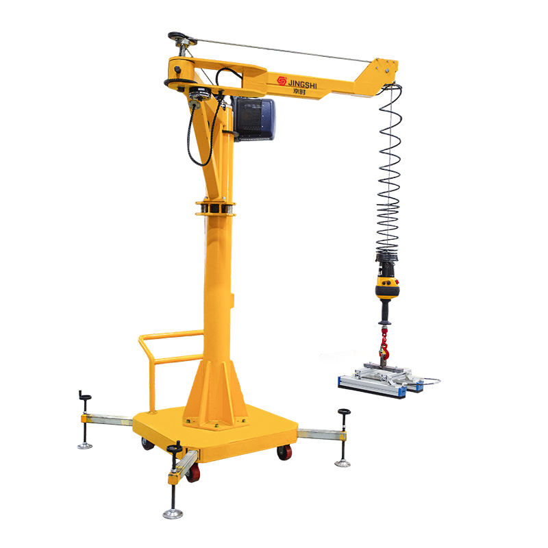
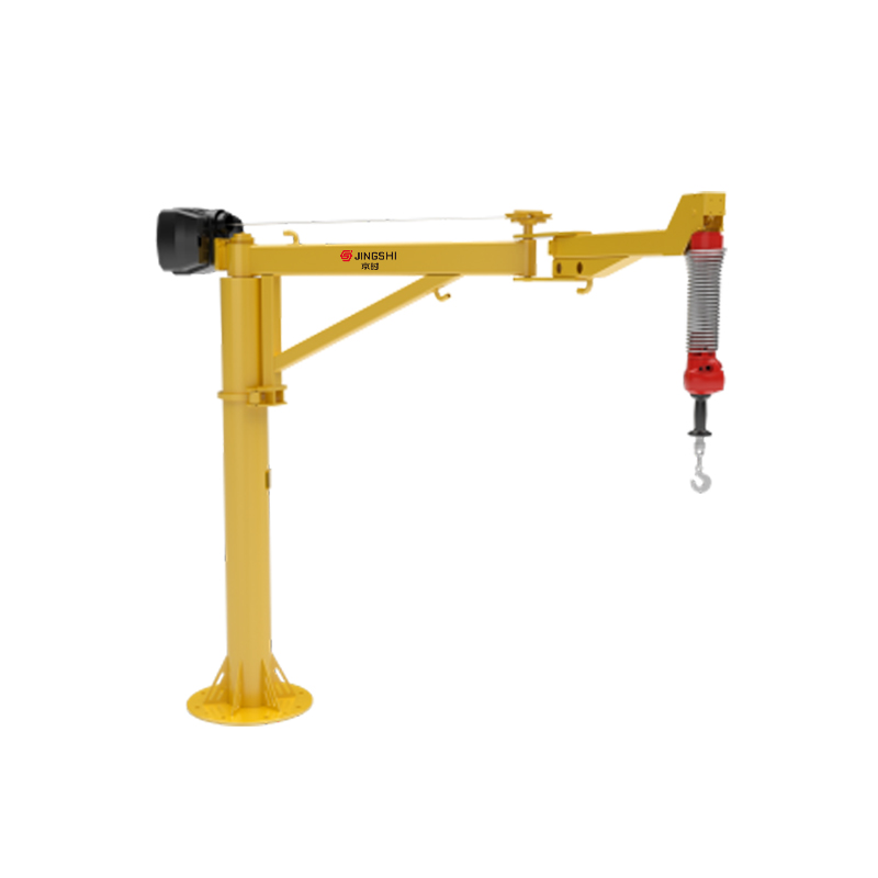
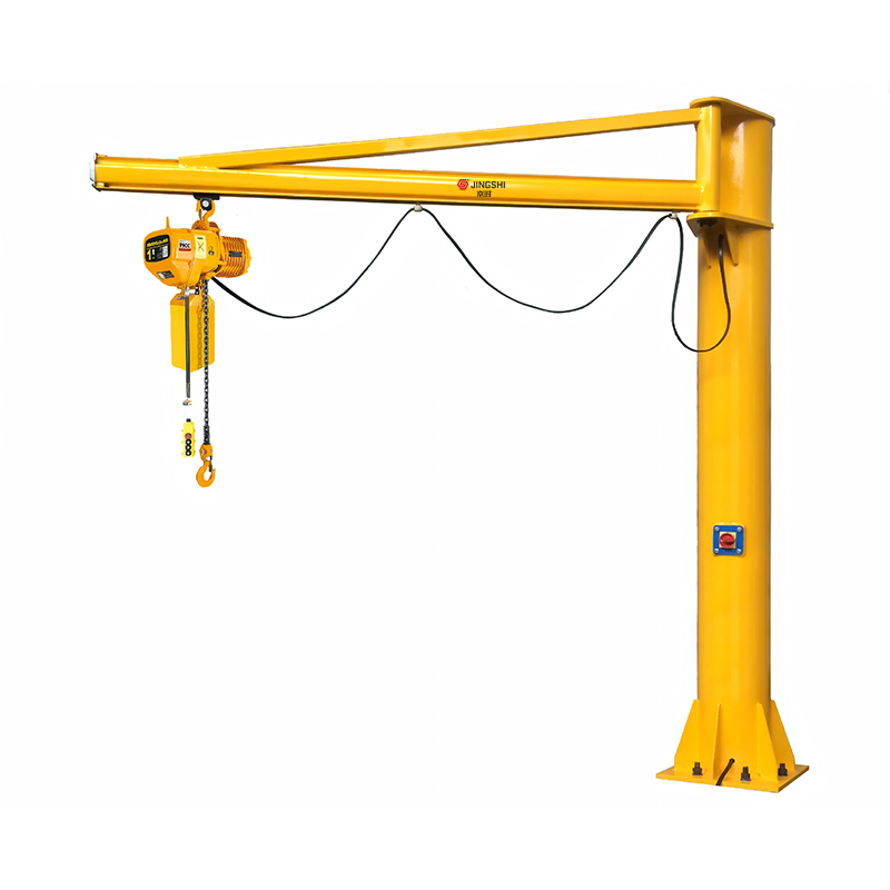
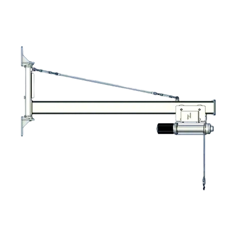
| Jib Crane | 3–12 m | 0.25–5 t | Wall or column-mounted, 180–360° rotation |
| Crawler Crane | Variable boom | 40–3,500 t | Distributed ground bearing, mobile lattice boom |
Box Girder vs. Truss Girder
For long-span overhead cranes, engineers must choose between box girder and truss girder construction. Box girders offer superior torsional rigidity and are favored for heavy-duty, high-cycle applications over spans exceeding 20 m. Truss girders are lighter and cheaper but require more maintenance access for joint inspection. A 30 m span box girder for a 50-ton crane will typically weigh around 18–22 tons of fabricated steel, compared to 12–15 tons for an equivalent truss design.
Material Selection and Weld Design
Structural steel grades used in crane fabrication are selected based on yield strength, toughness at operating temperature, and weldability. S355 (yield strength 355 MPa) is the most widely used structural grade in European crane manufacturing, while A572 Grade 50 is its North American counterpart. For cryogenic or polar operating conditions, Charpy impact testing at −40°C is a mandatory design requirement.
Weld Classifications and Fatigue
Weld detail categories (per EN 1993-1-9 or AWS D1.1) directly influence fatigue life. A full-penetration butt weld in a high-stress girder flange may be classified as Detail Category 71, meaning it can sustain 71 MPa stress range at 2 million cycles before fatigue failure becomes probable. Poor weld profiles, undercut, or lack of fusion can reduce that rating by 30–50%, which is why non-destructive testing (NDT) — including ultrasonic and magnetic particle inspection — is standard practice on crane girder welds.
Hoist and Drive System Design
The hoist mechanism is the functional core of any crane. Its design involves the wire rope system, drum geometry, gear train, braking system, and motor selection.
Wire Rope Selection
Wire rope is specified by construction (e.g., 6×36 IWRC), minimum breaking force, and fleet angle. A safety factor of at least 5:1 is required by most standards (ISO 4308, FEM 1.001). For a 10-ton hoist with a 4-part reeving system, the rope tension per line is approximately 2.5 tons, so a rope with a minimum breaking force of at least 125 kN is required.
Variable Frequency Drives (VFDs)
Modern crane hoists and travel drives are almost universally equipped with variable frequency drives. VFDs provide smooth acceleration, controlled deceleration, and precise positioning — reducing dynamic shock loads by up to 40% compared to direct-on-line motor starts. They also allow regenerative braking, which can return 15–25% of energy to the grid in high-cycle operations.
Safety Systems Integrated Into the Design
Safety is not an add-on in crane design — it is embedded in the engineering from the first load case. The following systems are standard requirements in most industrial and construction cranes.
- Load moment indicator (LMI): Continuously monitors the ratio of actual load to rated capacity, triggering alarms or lockouts when thresholds are exceeded.
- Overload protection: Mechanical or electronic devices that prevent hoisting beyond 110% of rated capacity (as required by EN 14492-2).
- End stops and buffers: Structural end stops absorb kinetic energy from trolley or bridge travel; hydraulic or polymer buffers are sized for maximum travel speed.
- Anti-collision systems: Used in facilities with multiple cranes on shared runways; laser or radar sensors maintain minimum separation distances.
- Emergency braking: Fail-safe spring-applied brakes engage automatically on power loss, critical for cranes handling molten metal or hazardous materials.
Deflection and Stiffness Limits
Girder deflection is a critical serviceability criterion, not just a structural one. Excessive sag under load affects hook path accuracy, causes uneven wheel loading, and accelerates rail and wheel wear. Most standards limit mid-span deflection to span/700 under rated load — so a 35 m span girder must not deflect more than 50 mm at full load.
For precision cranes in manufacturing or semiconductor environments, tighter limits of span/1000 or even span/1500 are sometimes specified. Achieving this with a lightweight structure requires pre-cambering the girder — a deliberate upward bow built into fabrication that compensates for expected dead load and live load deflection.
Design Standards and Certification Requirements
Crane design does not occur in a regulatory vacuum. The applicable standard depends on region, application, and crane type.
- FEM 1.001: European federation standard for overhead cranes, widely referenced for duty classification and structural calculation.
- ISO 4301 / ISO 4308: International standards covering classification systems and rope selection.
- EN 13001 series: European harmonized standard for crane safety, superseding many older national norms and required for CE marking.
- ASME B30 series: Dominant standard in North America; covers overhead, mobile, and tower cranes in separate volumes.
- OSHA 1910.179 / 1926.1400: U.S. regulatory requirements for general industry and construction cranes respectively.
Failure to comply with the applicable standard can invalidate insurance coverage and result in regulatory shutdown, making standards compliance a non-negotiable element of the design process.
Common Design Mistakes and How to Avoid Them
Even experienced engineers encounter recurring pitfalls in crane design. Understanding these helps teams build in margin and validation steps early.
- Underestimating duty class: Specifying a light-duty crane (A3) for an application that eventually sees A5 cycle rates leads to premature fatigue cracking in girder flanges and end carriage welds.
- Ignoring runway beam stiffness: A flexible runway structure amplifies dynamic loads on the crane. Runway deflection under load should not exceed span/600 per EN 1993-6.
- Overlooking wheel load distribution: Four-point loading analysis is often done assuming rigid structure; real-world flexibility means one wheel can carry up to 30% more than calculated.
- Insufficient corrosion allowance: Outdoor or process-environment cranes without adequate coating systems or material upgrades show measurable section loss within 5–7 years.
- Skipping FEA on complex geometries: Non-standard connections, cutouts in web plates, or asymmetric load paths should be validated using finite element analysis before fabrication.
Conclusion: Design Quality Determines Lifecycle Value
Crane design is a multi-disciplinary engineering task where structural analysis, mechanical systems, electrical controls, and safety engineering must align precisely. The most cost-effective crane is not the lightest or cheapest to fabricate — it is the one designed accurately for its actual duty cycle, environment, and longevity requirements. Investing in rigorous load analysis, appropriate material grades, validated weld details, and proper safety integration pays back through reduced downtime, fewer repairs, and a longer service life that can comfortably exceed 25–30 years in well-maintained installations.