 English
 русский
 Español
 عربى
عربى
JingShi
JingShi
JingShi
JingShi
JingShi
JingShi
JingShi
JingShi
JingShi
Content
- 1 What Is a Vacuum Lift Assist and How Does It Work?
- 2 Key Applications Across Industries
- 3 Fixed vs. Mobile Vacuum Lift Systems: A Side‑by‑Side Comparison
- 4 How to Select the Right Suction Cup for Your Material
- 5 Load Capacity & Safety: What You Need to Know
- 6 Integrating Vacuum Lift Assists with Overhead Cranes & Jib Cranes
- 7 Maintenance Checklist to Maximize Lifespan
- 8 ROI: How Much Can a Vacuum Lift Assist Save Your Operation?
What Is a Vacuum Lift Assist and How Does It Work?
Every year, US manufacturers report thousands of back injuries and hernias directly tied to manual lifting of heavy or awkward loads. A vacuum lift assist replaces that risk with a precision-controlled, air‑powered solution that can handle anything from 30‑lb boxes to 5,000‑lb metal plates. The concept is straightforward: a vacuum pump pulls air through a hose and a set of suction cups, creating a low‑pressure zone that grips the load securely. The operator guides the suspended load with fingertip controls, eliminating the need for hoists, chains, or excessive force.
Think of it as a mechanical arm that uses differential air pressure rather than clamps or magnets. Because no hard contact points dig into the part, surface‑sensitive materials—painted metal, polished glass, or printed packaging—move without scratches, dents, or distortion. This is exactly why precision sheet‑metal shops and high‑end appliance manufacturers have made vacuum lift assists a standard fixture on their shop floors.
The key hardware components are minimal but carefully engineered:
- Vacuum pump or venturi‑type ejector, sized for required flow and ultimate vacuum level
- Suction cups (also called vacuum pads) matched to material porosity and shape
- Control handle with integrated lift/lower and vacuum release triggers
- Flexible air hose and lift tube connecting the pump to the end‑effector
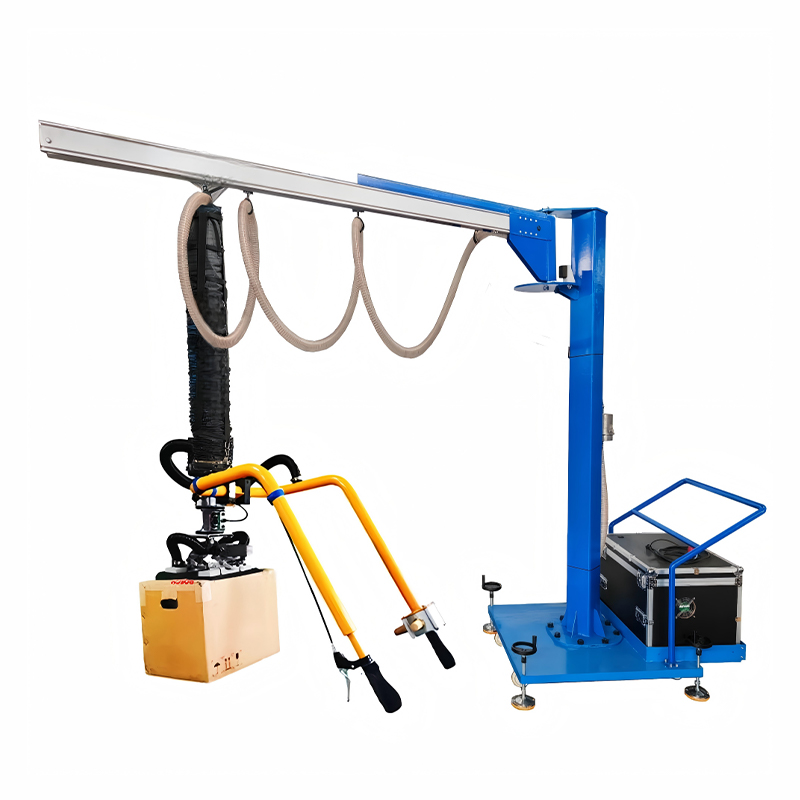
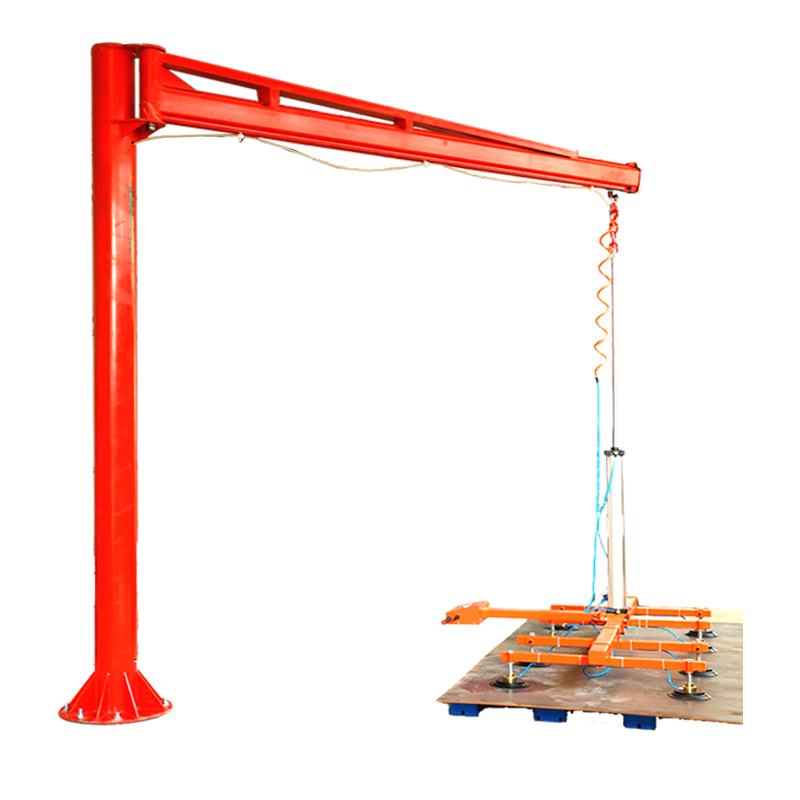
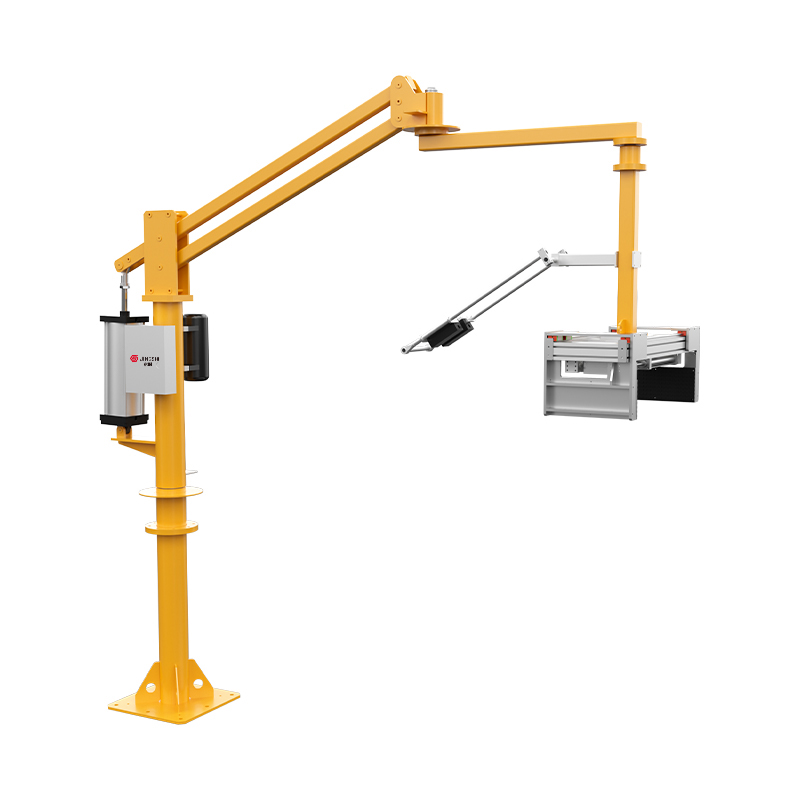
- Suspension interface — either a trolley‑mounted balancer, a jib crane hook, or a folding arm crane attachment
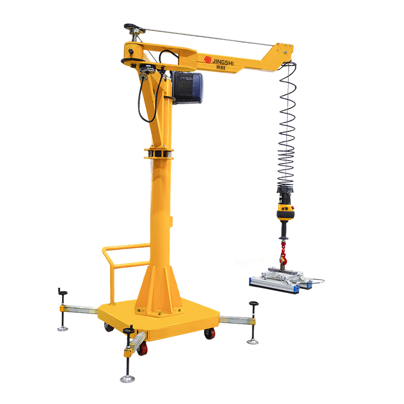
Unlike traditional slings or magnetic lifters, a vacuum lift assist applies force only where the cup seals. That distributed grip means flexible materials such as thin sheet metal won’t bend and porous items like cardboard boxes can still be lifted safely, provided the pump compensates for leakage.
Key Applications Across Industries
One misconception we often hear is that vacuum lifting only works on perfectly flat, non‑porous surfaces. In reality, modern high‑flow vacuum pumps and specialized cup skirts now grip everything from heavy steel plates to burlap sacks. The common thread across all industries is the need to protect workers while speeding up cycle times.
Here’s where vacuum lift assists prove their value every shift:
Metal Fabrication and Sheet Handling
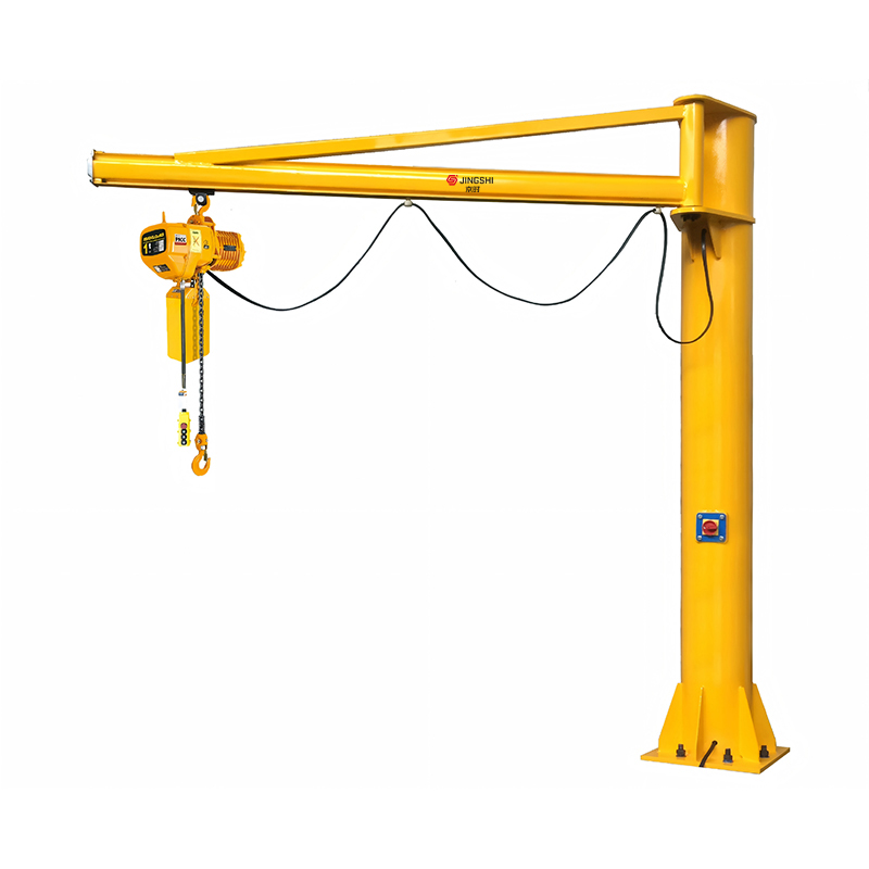
In a typical laser‑blanking or leveling line, operators must repeatedly unload flat metal sheets from a hydraulic leveling machine and transfer them to a stack or conveyor. Manual lifting of even a 50‑lb sheet 300 times a day invites fatigue and edge‑cut injuries. A vacuum lift assist mounted on a fixed jib crane lets one person maneuver sheets up to 1,000 lb without physical strain. The vacuum pad design ensures that freshly leveled, high‑tolerance blanks maintain their flatness — a critical advantage when working with parts destined for precision assembly like EV battery trays or aerospace skin panels.
Packaging and Palletizing
For boxes, bags, and consumer goods cases, a vacuum lift assist speeds up palletizing by 25–40% compared to manual stacking. Multi‑cup end‑effectors with foam or sponge pads spread the gripping force across the entire box surface, preventing crushing and maintaining packaging integrity. Food‑grade silicon cups are common here to meet FDA standards.
Glass and Stone Handling
Large glass panels for windows or solar modules present two challenges: weight and fragility. Vacuum lift assists with four or six large‑diameter cups distribute the lifting force, so a 200‑lb glass sheet can be rotated and positioned without edge pressure points. Rubber gaskets on the cups provide the necessary airtight seal without scratching.
Bagged and Porous Materials
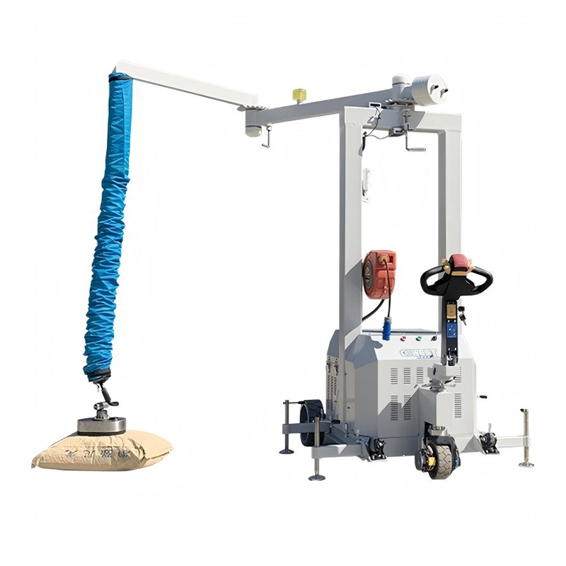
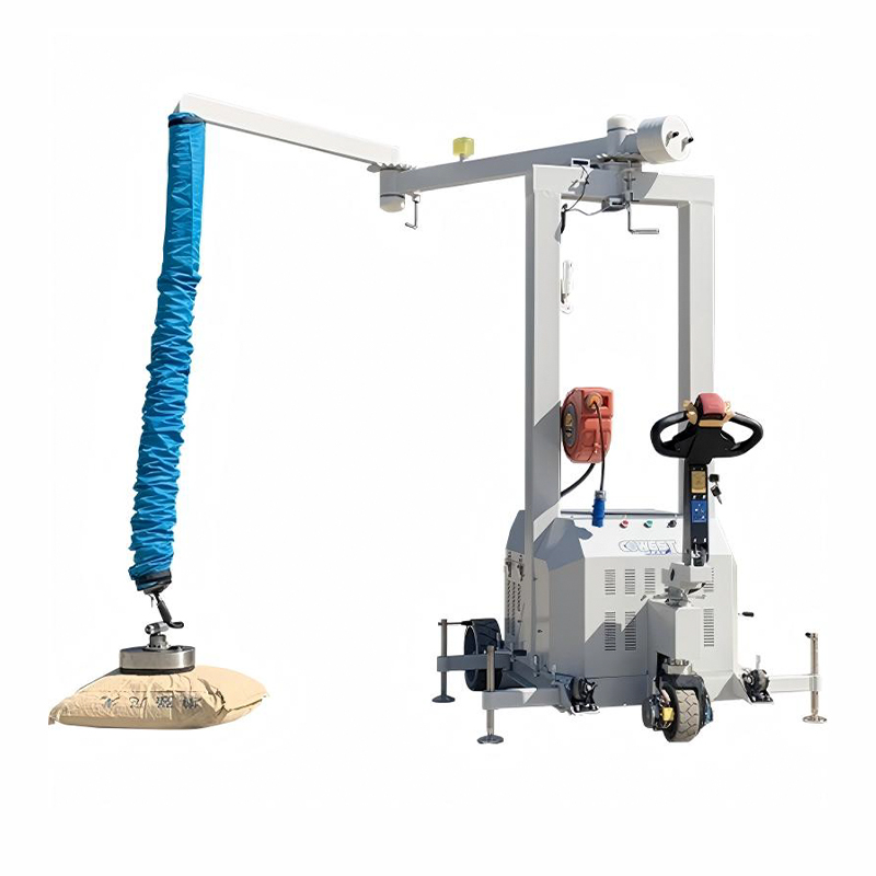
Flour, cement, chemicals — these arrive in paper or woven poly bags that allow air to leak through. The solution is a high‑flow vacuum pump (often above 200 L/min) and a large‑area suction foot with a compliant rubber skirt. Even with leakage, the pump maintains sufficient holding force. Operators can lift 110‑lb bags repetitively without bending, drastically cutting the incidence of musculoskeletal disorders.
Fixed vs. Mobile Vacuum Lift Systems: A Side‑by‑Side Comparison
Choosing between a fixed (overhead‑suspended) and a mobile (cart‑mounted) vacuum lift system is usually the first equipment decision you will make. Each configuration serves a distinct material flow pattern, and picking the wrong one can undermine your ROI. The table below breaks down the critical differences.
| Feature | Fixed System | Mobile System |
|---|---|---|
| Max Typical Load | Up to 2,000 lb (with multi‑cup arrays) | Typically 150–500 lb |
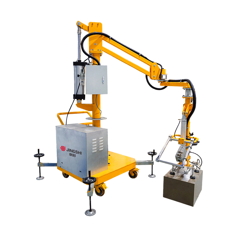
| Installation | Requires overhead steel (bridge crane or jib crane rail); permanent mounting | Self‑standing; plug‑and‑play with casters and integrated base |
| Flexibility | Limited to a defined working envelope (circular for jib, rectangular for bridge) | Can be rolled between workstations; ideal for multi‑cell production |
| Best For | High‑cycle, single‑location tasks like unloading a leveler or loading a press brake | Mixed‑duty environments with varying part sizes and low‑volume runs |
| Footprint | Zero floor footprint — all structure overhead | Floor space occupied by cart; turning radius must be allowed |
| Upgrade Path | Easy to integrate with powered trolleys and automation | May be upgraded with battery packs and extended reach arms |
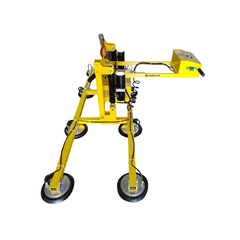
A fixed system connected to a fixed suction cup lifting machine often integrates with an overhead crane for straight‑line transfer from a coil leveling line to a stacking zone. Mobile units, on the other hand, serve smaller job shops where a single vacuum lift assist might handle raw material intake in the morning and finished‑goods palletizing in the afternoon. Whichever you choose, verify that the mounting interface matches your existing crane hook or trolley plate to avoid costly adapters.
How to Select the Right Suction Cup for Your Material
An ill‑chosen suction cup is the root cause of most vacuum lift failures — from sudden part drops to excessive surface marking. The cup must match three variables: material porosity, surface texture, and weight distribution. Use the selection matrix below as a starting point.
| Material Type | Recommended Cup Material | Preferred Shape | Key Consideration |
|---|---|---|---|
| Flat metal sheet (steel, aluminum) | Nitrile rubber (NBR) or polyurethane | Flat with inner support ribs | Oil‑resistant; 1.5 mm lip thickness to avoid marking |
| Cardboard box | Foam or sponge silicone | Large‑area rectangular pad | Compensate for surface leakage; high‑flow pump recommended |
| Glass panel | Natural rubber or silicone | Bellows (accordion) cup | No‑mark formulation; bellows absorb height variation |
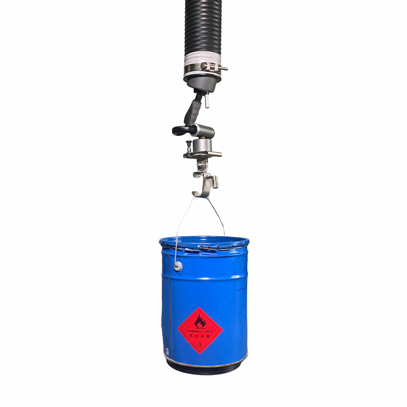
| Plastic tote / drum | Thermoplastic polyurethane (TPU) | Oval or round deep cup | May require a vacuum reservoir to handle flexing |
| Paper bag / woven sack | Rough‑surface rubber with skirt | Large flat foot with integrated foam | Leak‑tolerant design; min. 150 L/min pump flow |
For mixed‑material facilities, a quick‑change cup mounting system can reduce downtime to under 30 seconds. Our engineers often recommend keeping at least two cup sets on hand: one for non‑porous metals and another with a breather skirt for bagged goods. Also, check cup durometer: a 55 Shore A rubber will conform to slight curves, while a 70 Shore A is better for oily sheet stock.
Load Capacity & Safety: What You Need to Know
The maximum rated lift capacity of a vacuum assist is not simply the sum of each cup’s theoretical holding force. Safe operation demands a design factor of at least 1.5× for horizontal lifts and 2.0× for any tilting or rotation. A four‑cup array with 6‑inch diameter cups pulling 20 inHg can generate roughly 480 lb of total holding force on a clean, flat surface. Applying a 2.0× safety margin, the system should not be used to lift more than 240 lb in dynamic motion. That number drops further if the material is oily, curved, or flexible.
Always run a static pull test on a sample part at your facility. Attach a force gauge between the cup and the load, energize the vacuum, and slowly increase weight until the seal breaks. Multiply the measured breakaway force by 0.5 (for the safety factor) to find your operational limit. Document this for every part number, because surface finish variation between batches can alter grip by 15–20%.
Modern vacuum lift assists incorporate failsafes that go beyond the safety factor: check valves that hold vacuum for several minutes during power loss, audio/visual alarms when pressure drops below a set threshold, and spring‑loaded release mechanisms that prevent accidental drop even if the operator pulls the release handle fully. Look for systems with a redundant vacuum circuit if you handle high‑value components; the added cost is negligible compared to a single dropped part.
Integrating Vacuum Lift Assists with Overhead Cranes & Jib Cranes
Most vacuum lifters operate suspended from an overhead structure — whether a full bridge crane, a jib crane, or a cantilevered folding arm. The integration steps are straightforward but skipping any one can create a safety audit nightmare.
- Confirm the mechanical interface. Most lift assists ship with a top‑mounted U‑clevis or forged eye that fits a standard 1‑ton to 5‑ton capacity hook. If your crane uses a trolley plate instead, an adapter plate with appropriate grade‑8 bolts is required.
- Mount a balancer or air‑hoist, if needed. Some vacuum lift assist models combine an internal pneumatic balancer; others rely on an external hoist. For fine height control, a balancer that allows free‑floating movement in a 12‑inch window is ideal.
- Connect supply lines safely. The vacuum pump itself may be mounted on the trolley or on a separate stationary base with a long hose. Ensure the hose is supported with a festoon system so it never contacts the floor or becomes a trip hazard. If using an electric‑powered pump, confirm that the crane’s electrification is compatible (480 V three‑phase is common).
- Test the safety lock‑off. After installation, operate the crane with the vacuum assist unloaded. Verify that the emergency stop on the vacuum system halts all lifting and that the vacuum alarm functions. Record the vacuum decay time; a well‑sealed system should hold 80% of working vacuum for at least 3 minutes with a full load attached.
If your operation already uses a jib crane for manual lifting, adding a vacuum end‑effector to the existing hook is often a one‑day retrofit. This is especially practical in cells where sheets come directly off a hydraulic leveling machine — the same crane now handles both raw material and the vacuum assist, reusing the existing column and boom.
Maintenance Checklist to Maximize Lifespan
A vacuum lift assist with no moving parts on the end‑effector seems low‑maintenance, but neglect will erode performance quickly. We see an average lifespan extension of 2–3× when shops follow a structured checklist. The most critical items revolve around seal integrity and particulate contamination.
Print this schedule and post it at the maintenance board:
Daily
- Inspect all suction cups for cracks, tears, or permanent set (flattening). Replace any cup with a circumferential tear longer than 3 mm.
- Verify the audio/visual alarm triggers when the vacuum level drops 10% below setpoint during a simulated leak test.
- Check hose connections for tightness and kinks.
Weekly
- Use a handheld vacuum gauge to confirm that the pump reaches its published ultimate vacuum (e.g., 25 inHg) with the suction cup blocked off.
- Clean cup sealing lips with a damp, lint‑free cloth and a mild alcohol solution to remove oil and dust.
- Function‑test the release valve; it must drop the load within 0.5 seconds when actuated.
Monthly
- Remove and inspect the air filter element. Replace if visibly darkened or if vacuum level has dropped more than 2 inHg from baseline.
- Lubricate any moving joints on the balancer or trolley according to the manufacturer’s spec — usually a light ISO 32 hydraulic oil.
Quarterly
- Perform a full cup‑to‑pump vacuum decay test. Evacuate the system with a dummy steel plate, then turn off the pump. Log the time to reach 50% vacuum. A drop faster than previous quarters signals a seal issue.
- Torque‑check all structural fasteners on the suspension interface.
- If your pump uses oil, replace the oil and separator element.
One low‑cost tip: dull or glossy‑looking cup lips can often be restored by lightly sanding with 400‑grit paper to expose fresh rubber, extending cup life by months. This works particularly well for nitrile cups in oily environments.
ROI: How Much Can a Vacuum Lift Assist Save Your Operation?
Investment in a vacuum lift assist is rarely justified on ergonomics alone — management needs numbers. Fortunately, the direct savings are easy to isolate. Take a common scenario: an operator unloads 50‑lb metal sheets from a decoiler straightener feeder line onto a stack 5,000 times a year. Manual handling requires two workers, one on each side, totaling roughly 2 minutes per sheet when counting lift, walk, and position. With a vacuum assist, one operator completes the cycle in 45 seconds. At a $25 per hour fully‑burdened labor rate, the annual labor saving exceeds $26,000. The equipment cost for a mid‑range fixed vacuum lift system—including installation on an existing jib crane—typically runs between $18,000 and $30,000, meaning a payback inside 8 to 14 months.
Beyond direct labor, factor in reduced injury claims. OSHA data shows the average direct cost of a single back injury claim in manufacturing exceeds $40,000, not counting replacement training. Facilities that have adopted vacuum lifting consistently report a drop in recordable incidents by 60–80% within the first year. A single avoided injury effectively pays for the entire system.
Cycle time improvements create additional capacity without adding headcount. For high‑volume palletizers shifting from a manual to a vacuum‑assisted carton box vacuum lifter, productivity gains of 30% are common. That extra throughput often eliminates the need for a planned second shift, delivering six‑figure annual savings in a busy distribution center. When building your capital request, present the labor, safety, and capacity numbers together — the combined impact makes this one of the fastest‑paying automation investments on the factory floor.