 English
 русский
 Español
 عربى
عربى
JingShi
JingShi
JingShi
JingShi
JingShi
JingShi
JingShi
JingShi
JingShi
Content
- 1 Tight-Line (Stop-Go) vs. Free-Loop CTL: The Core Architectural Decision
- 2 Five Core Components — And What Each One Demands During Selection
- 3 How Material Specifications Dictate Line Configuration
- 4 Integrating CTL Output with Downstream Processes
- 5 Common Problems and Structured Troubleshooting
- 6 Safety and Maintenance: Two Sides of Uptime
A 20-ton coil of HSLA steel sits in your bay. By end of shift, it needs to be 4,000 flat, square sheets with a length tolerance of ±0.015 inch. The machine that makes or breaks this promise is a cut-to-length line. The wrong line configuration turns high-margin material into scrap. The right one delivers consistent blanks downstream processes can rely on.
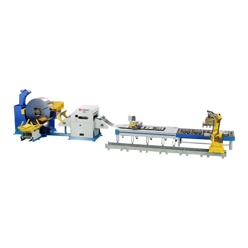
A cut-to-length line (CTL) transforms master coils into dimensionally precise sheets through a sequential process: uncoiling, leveling, measuring, shearing, and stacking. It differs fundamentally from a slitting line, which cuts a coil lengthwise into multiple narrower strips, and from a blanking line, which produces shaped, non-rectangular parts directly from coil stock. A CTL line produces only rectangular blanks — but it must produce them with repeatable length accuracy and flatness.
The signals you need to read before selecting a line are straightforward: material thickness, width, yield strength, coil weight, and target production rate. These inputs dictate whether you need a stop-go (tight-line) or a free-loop design, how many leveler rollers are necessary, and which shear type will hold tolerance. Let’s walk through those decisions systematically.
Tight-Line (Stop-Go) vs. Free-Loop CTL: The Core Architectural Decision
Every cut-to-length line falls into one of two fundamental architectures. The choice between them cascades into every other equipment specification.
A stop-go line, also called a tight-line CTL, accelerates the strip rapidly through the leveler, decelerates it to a complete stop, and triggers a stationary shear. The strip never accumulates in a loop. This design is inherently simpler. The capital cost is typically 25–40% lower than a comparable free-loop line, and the foundation costs drop as well because no looping pit is required. The thickness capacity is virtually unlimited, which makes stop-go lines the default choice for heavy-gauge processing above 0.250 inch, and often the only viable option above 0.500 inch.
That simplicity comes with a hard trade-off. Because the entire strip must stop for every cut, cycle rates drop sharply as sheet length increases. A stop-go line producing 120-inch blanks on thin material may achieve only 10–15 parts per minute. Meanwhile, the repeated acceleration and deceleration cycles can leave visible roll marks on sensitive surfaces — a critical defect in appliance or automotive exposed-panel applications.
A free-loop line solves this by separating the leveling and shearing operations with a material accumulation pit. The leveler runs at a near-constant speed, feeding a loop of material that floats freely. A high-speed flying shear at the exit cuts on the fly without ever stopping the strip. For light-gauge material under 0.125 inch, this architecture easily achieves 40–60 sheets per minute. Surface quality improves because the leveler never stops pressing against the same strip section.
The cost structure inverts, however. Free-loop lines require the looping pit, more sophisticated tension control, and a flying shear mechanism — pushing capital expenditure 30–60% higher. They also demand more floor space. The practical upper thickness limit for free-loop processing typically falls around 0.250 inch, after which strip stiffness prevents reliable loop formation.
| Criterion | Stop-Go (Tight-Line) | Free-Loop |
|---|---|---|
| Relative CapEx | Lower — typically 60–75% of equivalent free-loop | Higher — looping pit, flying shear, tension control |
| Production Rate | 10–30 sheets/min (length-dependent) | 40–60+ sheets/min for thin gauge |
| Max Practical Thickness | 1.000 inch or more — effectively unlimited | ~0.250 inch — limited by strip stiffness in loop |
| Surface Quality | Risk of roll marks on sensitive surfaces | Excellent — continuous motion preserves finish |
| Floor Space | Compact — no looping pit required | Larger — pit and extended line length |
The decision rule is surprisingly clean: if the majority of your product mix falls below 0.125 inch and throughput matters, bias toward free-loop. If you process plate, heavy structurals, or a wide thickness mix that exceeds 0.250 inch, stop-go is the pragmatic choice. Service centers running both extremes sometimes operate two separate lines rather than compromising either end of the range.
Five Core Components — And What Each One Demands During Selection
A CTL line is a chain of specialized machines. A weak link anywhere in that chain becomes the line’s throughput bottleneck. Here is what to scrutinize in each component.
Decoiler (Uncoiler)
The decoiler holds the master coil and feeds strip into the line at controlled tension. Two parameters dominate the selection: mandrel expansion range and coil weight capacity. The mandrel must grip the inner diameter of your coils securely. For plants running multiple coil ID sizes, a decoiler with a wide expansion range — or quick-change mandrel segments — eliminates costly downtime. Coil weight capacity directly limits your maximum run time between coil changes. Under-specifying coil weight capacity is one of the most common regrets in CTL procurement: a decoiler rated for 20,000 lb becomes a bottleneck the moment procurement lands an attractive 30,000-lb master coil opportunity.
For heavy-gauge lines, a hold-down arm or pressure roll on the decoiler prevents the outer coil wraps from springing open. For light-gauge lines running thin, tension-sensitive material such as aluminum, a driven decoiler with closed-loop tension feedback prevents strip scratching and width necking.
Leveler (Flattener)
The leveler is where flatness is won or lost. Roller count, roller diameter, and roll material directly determine what flatness tolerance the line can achieve. A 17-roller leveler provides adequate correction for commercial-quality sheet where ±0.060 inch flatness deviation is acceptable. Moving to a 21-roller configuration, with smaller work roll diameters and tighter center distances, enables precision flatness in the ±0.020 inch range — the requirement for laser-cutting blanks or automotive outer panels.
Roller backing support matters equally. For materials with yield strengths above 50 ksi, the leveler’s backup rolls must prevent work roll deflection under high separating forces. Hydraulic leveling machines with servo-controlled roll gaps outperform mechanical levelers here, especially on thin plate and material with unpredictable springback. Hydraulic systems adjust the roll position dynamically to maintain consistent penetration, while mechanical screw-down systems apply a fixed setting that cannot compensate for coil-to-coil property variation.
Shear
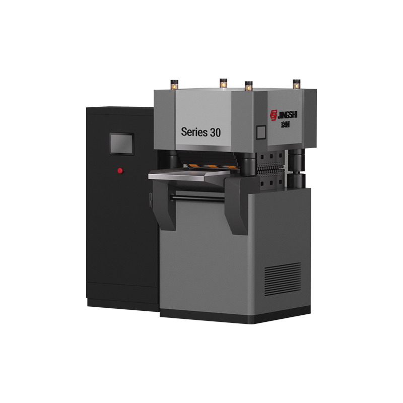
Stationary shears — either hydraulic or mechanical — pair with stop-go lines. Their cutting force rating must accommodate the maximum material cross-section: thickness × width × shear strength. For a 72-inch wide line cutting 0.500-inch HSLA at 80 ksi shear strength, the shear force requirement approaches 1,440 tons. Undersizing the shear produces burred edges and shortens blade life dramatically.
Flying shears pair with free-loop lines. They travel with the strip during the cut stroke and return for the next cycle. Rotary drum shears dominate thin-gauge, high-speed applications. Guillotine-style flying shears handle thicker gauges up to approximately 0.250 inch while maintaining squareness.
Blade clearance is the single most influential adjustment on cut quality. For mild steel, the rule-of-thumb clearance is 8–10% of material thickness. Operating outside this band — too tight or too open — produces the edge burr that later damages forming dies downstream.
Stacker
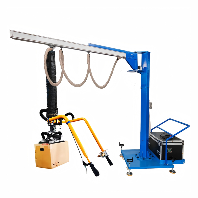
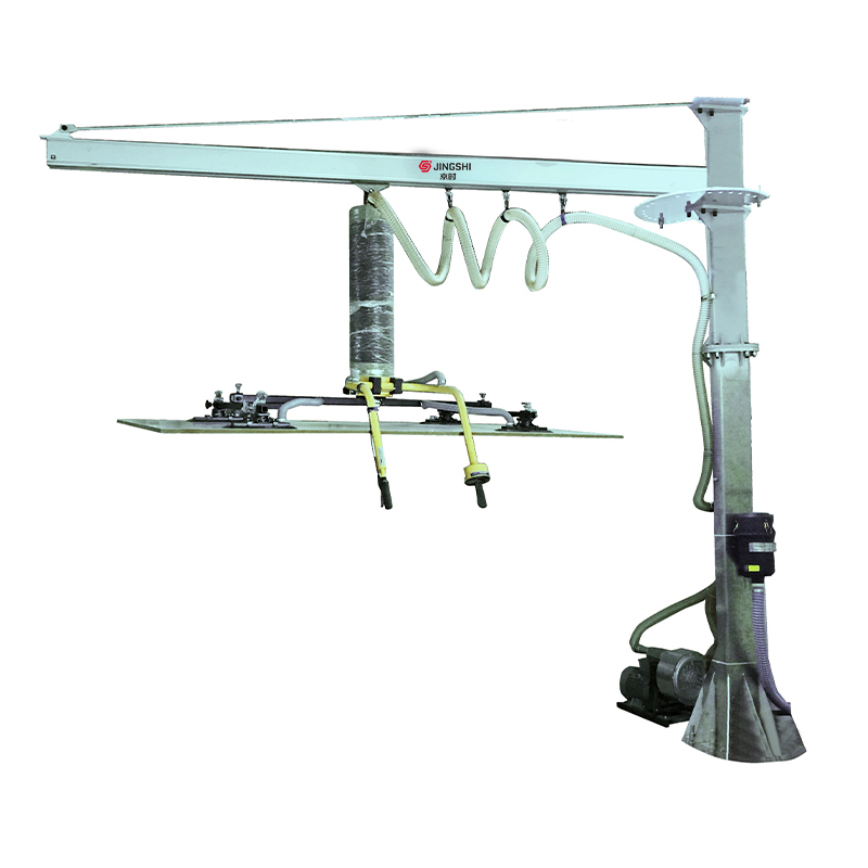
The stacker must receive cut sheets at line speed, align them into a neat bundle, and discharge the stack without interrupting production. Magnetic stackers serve ferrous materials reliably. For non-ferrous metals such as aluminum, brass, or copper — or for coated steel where magnets could mar the surface — vacuum-based stacking systems or vacuum lifting equipment built into the stacking area preserve surface quality. Stacker selection also depends on sheet size range: a stacker sized for 48-inch-wide sheets will struggle to handle 72-inch-wide product without jamming or misalignment.
Control System
Modern CTL lines rely on servo-driven measurement rolls and closed-loop length correction. A measurement encoder on a dedicated roll — not on the leveler or decoiler — tracks actual strip travel. Any slip between the measurement roll and strip surface translates directly into length error. The control system compares measured length against the setpoint and adjusts the shear trigger on the fly. For lines targeting ±0.010 inch length tolerance, this closed-loop architecture is mandatory; open-loop “fire on count” systems drift with temperature, speed, and material surface condition.
How Material Specifications Dictate Line Configuration
Every material parameter narrows the viable CTL configuration space. Thickness is the most decisive. For material below 0.118 inch (3.0 mm), a free-loop line with a high-speed flying shear delivers both throughput and flatness. For material above 0.250 inch (6.35 mm), stop-go with a hydraulic stationary shear is effectively mandatory — the strip cannot form a stable loop, and the shear forces exceed practical flying-shear designs.
Width dictates the roller face lengths on both the leveler and the shear, as well as the stacker throat. Coil width also interacts with flatness requirements: a 72-inch-wide sheet at 0.060 inch thick requires far more leveling support than a 24-inch-wide sheet of the same thickness, because the width-to-thickness ratio amplifies buckling tendencies.
Yield strength determines the leveler’s required separating force. Processing 100-ksi-yield AHSS requires a substantially different leveler frame and roll support design than processing 30-ksi-yield mild steel. The same physical roller configuration that levels mild steel may lack the structural rigidity to flatten high-strength material without deflecting. Overlooking this leads to permanent crown defects across the sheet width.
Surface quality requirements drive two decisions. First, whether the line runs in stop-go or free-loop mode, as discussed. Second, whether the leveler uses chrome-plated rolls (which resist galling on aluminum and galvanized coatings) or standard hardened steel rolls. For exposed automotive and appliance surfaces, chrome-plated work rolls plus continuous line motion are baseline requirements, not optional upgrades.
| Thickness Range | Recommended Architecture | Typical Shear Type | Typical Leveler Type |
|---|---|---|---|
| 0.012–0.118 inch (0.3–3.0 mm) | Free-loop | Rotary drum flying shear | 21-roller precision leveler |
| 0.118–0.250 inch (3.0–6.35 mm) | Free-loop or stop-go (application-dependent) | Guillotine flying shear or stationary hydraulic | 17–21 roller leveler |
| 0.250–1.000+ inch (6.35–25+ mm) | Stop-go (tight-line) | Stationary hydraulic shear | Heavy-duty 13–17 roller leveler |
Integrating CTL Output with Downstream Processes
A cut-to-length line rarely operates in isolation. The blanks it produces feed press lines, laser cutting cells, roll forming mills, or welding stations. Designing the CTL line without considering these downstream interfaces creates expensive mismatch.
Timing synchronization is the first interface. A CTL line running at 50 sheets per minute cannot feed a stamping press consuming 15 strokes per minute directly. The buffer between them — typically an accumulation conveyor or a sheet destacker — absorbs the speed differential. But the buffer capacity must be sized correctly. Too small, and the CTL line stops every few minutes waiting for the press to catch up. Too large, and work-in-process inventory balloons.
Flatness tolerance propagates downstream with a multiplier effect. A blank with 0.040 inch of edge wave that enters a CNC laser cutter may lift off the cutting bed enough to disrupt the laser focus, producing poor edge quality. A formed part stamped from a blank with residual stress from inadequate leveling will spring back unpredictably after forming. These failure modes trace directly back to the leveler configuration decision made during CTL specification. Lines feeding coil leveling and cutting systems that feed directly into stamping presses demand the tightest flatness specifications.
Stack orientation and labeling matter for traceability. In many operations, the CTL stacker must align sheets so downstream automation can pick them consistently — whether by robot gripper, vacuum cup array, or magnetic fan. Sheet-to-sheet stickiness from oil or coating can cause double-sheet pickups. A stacker with an air-knife separation system or mechanical peel-off feature prevents this fault at the source, before it jams the downstream cell.
Common Problems and Structured Troubleshooting
When a CTL line produces out-of-spec output, the root cause usually traces to one of three systems. Here is how to narrow the search quickly.
| Problem | Likely Cause | First Checkpoint | Second Checkpoint |
|---|---|---|---|
| Shear burr on cut edge | Incorrect blade clearance or dull blades | Measure blade gap with feeler gauge — confirm 8–10% of material thickness for mild steel | Inspect blade edge under magnification for chipping or radius exceeding 0.004 inch |
| Wavy or rippled sheet edges | Insufficient leveler penetration or worn backup rolls | Verify leveler roll position relative to material thickness setting; check for deflection under load | Inspect backup roll bearings for radial play exceeding 0.002 inch |
| Feed slippage, inconsistent length | Low strip tension or worn measurement roll surface | Confirm decoiler back-tension setting; strip should not be loose entering leveler | Check measurement roll surface roughness — re-texture if polished smooth by abrasive material |
Shear burrs are the most frequent complaint. Beyond blade clearance, the shear entry side guide alignment also contributes — if the strip enters the shear at a slight angle, one blade shoulder carries disproportionate load, accelerating wear on that edge. Shim checks once per shift on blade parallelism prevent gradual drift from becoming scrap production.
Leveler-induced flatness defects often appear only after the sheet cools or rests. A sheet that measures flat immediately after the line but develops a wave overnight contains residual stress that the leveler did not fully relieve. The correction is deeper leveler penetration — typically increasing the work roll intermesh by 0.005–0.010 inch increments until the stress relaxes. But going too far over-bends the material and creates a center buckle instead. Systematic increment adjustment is the only reliable method.
Safety and Maintenance: Two Sides of Uptime
CTL lines present concentrated hazards: rotating mandrels under high torque, exposed shear blades, and multi-ton moving coils. The safety protocols must be procedural, not aspirational.
- Shear zone guarding with interlocked entry doors is non-negotiable. The interlock circuit must physically disconnect shear actuation power — software-only interlocks fail dangerously when a PLC output sticks on.
- Coil loading requires a coil car with lateral restraint or a coil upender that prevents the coil from tipping during mandrel insertion. A coil that rolls off the loading zone carries enough energy to cause fatal injury.
- Emergency stop circuits need redundant contacts and must be tested under load monthly. A mushroom button that works when pressed lightly may fail under the high current of an actual fault.
On the maintenance side, a disciplined checklist prevents the gradual degradation that operators learn to tolerate. Leveler roll surfaces should be inspected weekly for surface damage — a single scored roll transfers its defect pattern to every sheet that passes over it. Backup roll bearings need grease purging on a schedule tied to operating hours, not calendar months, because high-speed lines accumulate bearing revolutions far faster than anticipated. Shear blade clearance requires shift-level verification when running abrasive or high-strength material that accelerates blade wear.
Measurement roll calibration warrants monthly attention. A measurement roll circumference that wears down by 0.005 inch introduces a systematic length error that accumulates across thousands of sheets before anyone notices. Keeping a calibration log and comparing actual sheet length against setpoint with a calibrated tape or laser system catches the drift early.