English
 русский
 Español
 عربى
عربى
JingShi
JingShi
JingShi
JingShi
JingShi
JingShi
JingShi
JingShi
JingShi
Content
- 1 How Vacuum Material Handling Systems Work
- 2 Main Types of Industrial Vacuum Handling Systems
- 3 Core Components and What They Mean for Performance
- 4 What Materials Can Vacuum Systems Handle
- 5 Safety, Ergonomics, and Workplace Compliance
- 6 Industry Applications Across Manufacturing and Logistics
- 7 Selecting the Right Vacuum Material Handling System
How Vacuum Material Handling Systems Work
Every vacuum material handling system operates on the same physical principle: remove air from a sealed space, and the pressure difference between that space and the surrounding atmosphere creates a holding force. The greater the pressure differential and the larger the sealing surface, the stronger the grip. In practice, a vacuum pump or generator evacuates a chamber formed between a suction cup and the workpiece surface, generating enough force to lift, move, and precisely position loads that would otherwise require multiple workers, slings, or mechanical clamps.
Vacuum levels determine what a system can realistically handle. Low vacuum (above 1 Torr) covers the majority of general industrial lifting and handling applications — sheet metal, glass panels, wooden boards, and similar flat materials. Medium vacuum levels serve more demanding manufacturing and processing tasks, while high vacuum is reserved for specialized applications such as semiconductor handling or cleanroom environments. For most fabrication and logistics settings, a well-specified low-to-medium vacuum system delivers the combination of holding force and cycle speed the application requires.
The practical advantage over mechanical gripping is surface preservation. Vacuum contact distributes load evenly across the suction area without applying point loads, clamping pressure, or edge forces — a critical factor when handling finished surfaces, precision-cut metal plate, polished glass, or laminated composites where surface damage is unacceptable.
Main Types of Industrial Vacuum Handling Systems
Vacuum material handling covers a wide range of equipment configurations. The right type depends on load weight, workpiece geometry, how frequently lifts are performed, and whether the system needs to be fixed in place or moved across a facility.
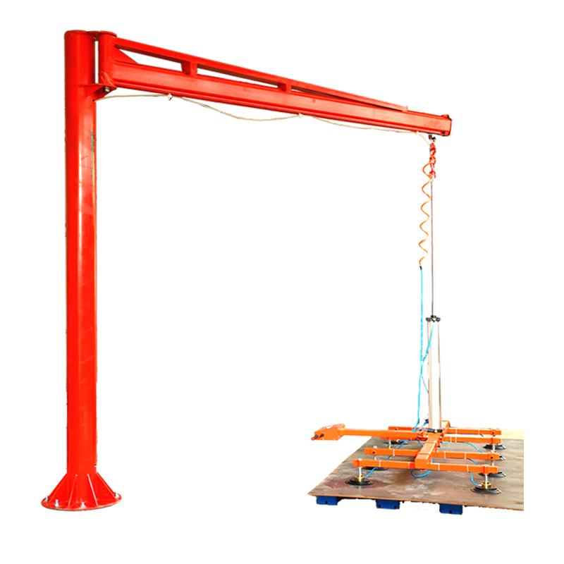
- Vacuum lifters (suction cup lifters) — The most common configuration for sheet and plate handling. A frame fitted with one or more suction cups connects to an overhead crane, jib crane, or hoist, allowing a single operator to lift, tilt, rotate, and position flat or slightly curved materials. Available in fixed and mobile variants to match different facility layouts. See the full vacuum lifter product range for industrial applications for configuration options.
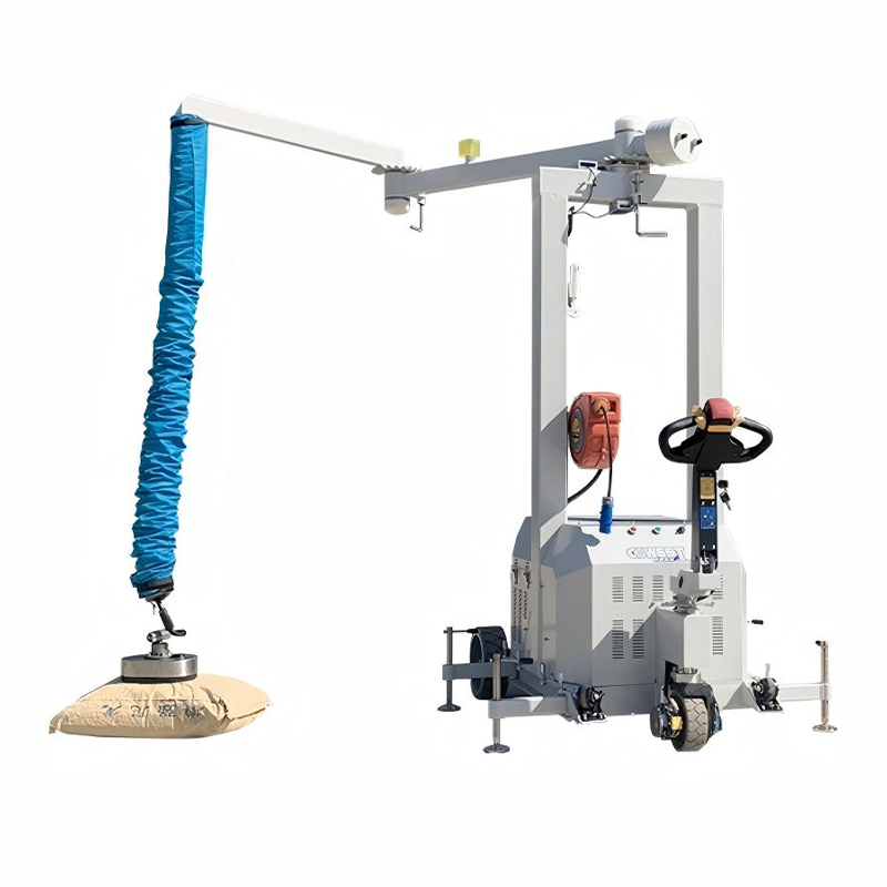
- Mobile vacuum lifting machines — Self-contained, wheeled units that combine the vacuum pump, suction frame, and lifting mechanism in one mobile package. Ideal for facilities where workpieces are handled at multiple stations or where overhead crane coverage is limited. A mobile suction cup lifting machine for flexible operations eliminates the need for fixed infrastructure and supports rapid repositioning across a workshop.
- Fixed vacuum lifting stations — Permanently installed at a specific workstation, typically integrated into a production line. Suited to high-throughput environments where the same lift cycle is repeated continuously. A fixed suction cup lifting machine for stationary workstations offers consistent positioning accuracy and reduced setup time per cycle.
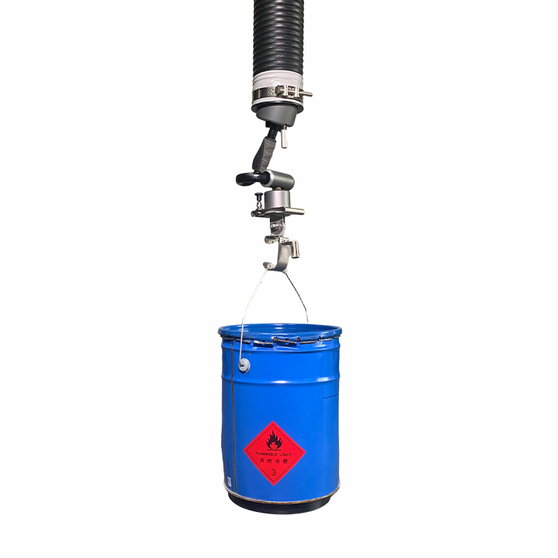
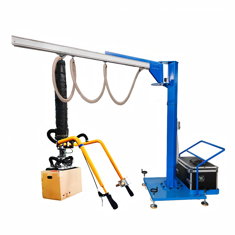
- Vacuum tube lifters — Lightweight, ergonomic devices suspended from an overhead rail or jib arm. The operator uses a hand lance with an integrated suction cup to pick and place smaller items at high frequency. Common in packaging, assembly, and order-picking environments.
- Pneumatic vacuum conveying systems — Used to transfer bulk powders, granules, and pellets through enclosed pipe networks using negative pressure. A distinct application from lifting — here the vacuum moves material horizontally or vertically between process stages rather than lifting discrete workpieces.
Core Components and What They Mean for Performance
Specifying a vacuum handling system requires understanding what each component does — and how its quality affects reliability, cycle time, and maintenance cost over the system's working life.
- Suction cups — The interface between the system and the workpiece. Cup geometry (flat, bellows, oval, rectangular) determines what surface profiles can be handled. Material selection — nitrile, silicone, polyurethane, or specialized compounds — dictates chemical resistance, temperature range, and surface compatibility. Worn or incorrectly specified cups are the most common cause of lifting failures. For maintenance guidance, see these tips for maintaining suction cup performance.
- Vacuum pump or generator — The power source for the system. Electric-driven vacuum pumps offer consistent performance independent of compressed air supply and are common in fixed installations. Venturi-type vacuum generators run on compressed air and have no moving parts, making them suited to environments where compressed air is already available and minimal maintenance is preferred.
- Filtration — Filters protect the pump from fine particles, coolant mist, and debris that can enter through the suction cups during handling. Blocked or absent filtration is a leading cause of premature pump failure. Filter specification should match the particle types and sizes present in the operating environment.
- Vacuum sensors and safety valves — A properly equipped system continuously monitors vacuum level and triggers an alarm — or holds the load with a check valve — if the pump fails or a leak develops. This is not optional safety theater; it is the mechanism that prevents uncontrolled load drops. For a deeper technical breakdown of how these components interact, see this guide on how vacuum lifting devices work and how to choose one.
- Control system — Ranges from a simple manual valve to a full PLC-integrated control panel with programmable lift sequences, vacuum level logging, and integration with production line controls. Automation compatibility becomes critical when the vacuum system is part of a larger material flow line.
What Materials Can Vacuum Systems Handle
Vacuum handling works reliably on any material that presents a sufficiently smooth, non-porous surface for the suction cup to seal against. The practical range is broad — but there are important limits to understand before specifying a system.
| Material Type | Compatibility | Key Considerations |
|---|---|---|
| Steel plate (mild, stainless) | Excellent | Surface finish affects seal quality; oil or coolant film is acceptable with correct cup material |
| Aluminum sheet and plate | Excellent | Softer surface requires non-marking cup materials; wide suction pads distribute load evenly |
| Glass panels | Excellent | Standard application; cup size and count must be calculated for the panel weight and dimensions |
| Wood panels and MDF | Good | Raw MDF is moderately porous — sealed or laminated surfaces perform better |
| Composites and plastics | Good | Surface texture and porosity vary by type; testing recommended before full deployment |
| Perforated or mesh plate | Not suitable | Vacuum cannot be maintained; magnetic or mechanical handling required |
| Rough castings or forgings | Limited | Surface irregularity prevents consistent sealing; specialized bellows cups may help on some profiles |
For flat plate and panel applications specifically, the complete buying guide for vacuum panel and sheet lifters provides detailed guidance on matching cup configuration to panel size, weight, and surface condition.
Safety, Ergonomics, and Workplace Compliance
Musculoskeletal disorders (MSDs) from manual lifting and repetitive handling represent one of the most costly categories of workplace injury in manufacturing and logistics. OSHA's ergonomics guidelines for material handling tasks emphasize designing work so that mechanical lifting aids replace manual exertion wherever feasible — and vacuum handling systems are one of the primary tools used to achieve this. OSHA's technical guidance on material handling task design specifically identifies conveyors, mechanical lifts, and ergonomic handling equipment as the appropriate engineering controls for reducing manual lifting risk.
Vacuum systems address the problem at the source: a single operator can safely handle loads that would otherwise require two or three workers, eliminate the awkward postures associated with manual gripping and carrying, and reduce the cycle-to-cycle fatigue that leads to errors and injuries over a shift. For tasks where full vacuum lifting is not practical, power-assisted manipulator solutions for ergonomic handling offer a complementary approach for positioning and assembly work.
From a compliance standpoint, several operational practices are non-negotiable regardless of system type:
- Pre-lift inspection of suction cups, hoses, and vacuum level indicators before each shift
- Never lifting loads over personnel — vacuum systems hold loads by pressure differential, and any seal failure is immediate
- Rated load capacity must include the weight of the lifting frame and any attachments, not just the workpiece
- All operators must be trained on emergency procedures for vacuum loss, including load securing and controlled lowering protocols
- Cups, seals, and filters must be on a documented maintenance and replacement schedule
Industry Applications Across Manufacturing and Logistics
Vacuum material handling systems appear in virtually every sector that moves flat, smooth, or panel-format materials at scale. The specific configuration — cup layout, system capacity, mounting method — changes by application, but the productivity and safety case is consistent across industries.
- Metal fabrication and laser cutting — Sheet metal needs to be loaded onto cutting tables, repositioned between operations, and unloaded as finished blanks, often at high frequency. Vacuum lifters dramatically reduce the labor required for these moves and eliminate surface marking that mechanical handling would cause on finished parts.
- Glass manufacturing and installation — Large glass panels cannot be handled with clamps or slings without risk of edge damage or breakage. Vacuum is the standard handling method across flat glass production, glazing, and curtain wall installation.
- Automotive stamping and body assembly — Blank sheet is loaded into stamping presses and finished panels are transferred between assembly stations using vacuum end-of-arm tooling. The precision positioning vacuum affords is essential for high-speed automated lines.
- Aerospace component handling — Aluminum and composite skins, structural panels, and finished assemblies are handled with vacuum to avoid surface contamination and mechanical damage. The non-contact nature of vacuum gripping is often a specification requirement in aerospace quality systems.
- Warehousing and logistics — Palletizing and depalletizing large, flat cartons, panels, or sheet goods with vacuum end-of-arm tooling on robotic cells or manual vacuum lifters significantly increases throughput compared to manual handling.
- Stone and tile installation — Heavy stone slabs and large-format tiles are routinely moved and positioned using portable vacuum lifters, eliminating the manual lifting that would otherwise require multiple workers and create MSD risk.
Selecting the Right Vacuum Material Handling System
A structured evaluation process prevents the two most common specification errors: under-sizing a system so it cannot reliably handle the intended load, or over-engineering a complex automated solution for an application that a straightforward manual vacuum lifter would serve equally well.
- Define maximum load weight and dimensions. This sets the minimum required lifting capacity. Factor in the weight of the lifting frame, hoses, and any attachments — the rated load is the net capacity available for the workpiece after equipment weight is accounted for.
- Characterize the workpiece surface. Smooth, non-porous surfaces (steel, glass, laminated wood) are straightforward. Slightly porous, textured, or oily surfaces require specific cup materials and may require a higher-capacity pump to compensate for minor leakage. Perforated or very rough surfaces disqualify vacuum as the primary handling method.
- Determine the required lift geometry. Does the load need to tilt from horizontal to vertical (common in plate loading operations)? Does it need to rotate? The number and arrangement of suction cups, and whether the frame needs articulation, depend on these requirements.
- Assess how and where the system will be used. A fixed production line station points toward a fixed vacuum lifting machine integrated with the line controls. A workshop where loading positions change regularly calls for a mobile system. A maintenance or installation crew working across different sites needs a portable, self-contained unit.
- Confirm power source availability. Electric vacuum pumps need a reliable power supply. Pneumatic venturi generators need a compressed air supply at sufficient flow rate — undersized compressors are a common cause of poor vacuum performance in the field.
- Set safety requirements. Specify whether the application requires a fail-safe vacuum retention mechanism (check valve to hold the load on pump failure), an audible/visual alarm for low vacuum, or integration with a safety PLC that prevents crane movement below a minimum vacuum threshold.
- Plan for maintenance access. Suction cups, seals, and filters are consumable items. Systems where these components are difficult to access or replace will accumulate deferred maintenance — and deferred maintenance on vacuum lifting equipment is a safety liability.