 English
 русский
 Español
 عربى
عربى
JingShi
JingShi
JingShi
JingShi
JingShi
JingShi
JingShi
JingShi
JingShi
Content
- 1 Engineering Design Principles for Steel Coil Machinery
- 2 Precision Machining and Component Manufacturing
- 3 Assembly, Alignment, and Hydraulic Integration
- 4 Testing, Quality Inspection, and Factory Acceptance
- 5 From Single Machines to Integrated Coil Processing Lines
- 6 What to Evaluate When Choosing a Steel Coil Machinery Supplier
A coil of hot-rolled steel arrives at the plant with internal residual stress, edge waves, and a thickness crown across its width. If that material is fed directly into a stamping press or a laser cutting table, the first parts can be out of tolerance before the operator identifies flatness as the cause. Steel coil machinery exists to make the input predictable: it flattens, feeds, and processes coils so that downstream operations can hold their dimensions. The design and production of steel coil machinery determine whether that predictability is achieved or lost. Two machines with the same roll count can perform completely differently on the shop floor, and the difference is created by engineering decisions made long before the machine is painted.
Engineering Design Principles for Steel Coil Machinery
Design work begins with the material envelope, not with a catalogue. The engineering team must define the yield strength range, thickness range, width range, and the flatness tolerance the customer has to hold. These four inputs decide the frame stiffness, the work roll diameter, the backup roll configuration, and the hydraulic force capacity.
The frame is the foundation of the machine. In heavy-duty equipment, a closed welded steel structure, stress-relieved and machined in a single setup on a large boring machine, keeps deflection low under full load. Frame deflection changes the roll gap, and because the gap controls the amount of plastic deformation applied to the strip, rigidity translates directly into flatness.
Work roll and backup roll layout is the next critical decision. Smaller work roll diameters create higher specific pressure on the strip, which is necessary for flattening harder or thinner material. Smaller rolls also deflect more, so the backup roll arrangement must support them across the full working width. The interaction between roll bending, backup roll support, and hydraulic adjustment is the design detail that separates precision equipment from general-purpose machinery.
Material compatibility is equally important. Work rolls need high hardness and good wear resistance, chromium plating protects the roll surface against rust and strip marking, and wipers plus lubrication systems keep scale and debris away from the sheet. These decisions affect not only flatness but also surface quality, which is a growing requirement in automotive and appliance component manufacturing.
For buyers specifying a new leveler, the differences in frame construction, roll support, and hydraulic design are visible in the engineering drawings and in the weight of the frame components. A machine such as the 40-series heavy-duty hydraulic precision leveling machine is built for plants where the material range includes high-strength steel and where frame deflection is not an option.
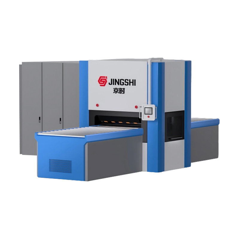 Heavy-Duty Steel Plate Leveling Machine | 0.6-4mm, ±0.01mm Precision | JingShiAs Hydraulic Steel Plate Leveling Machine Manufacturers and Plate Leveling Machine Suppliers in China, JingShi offer Steel Plate Leveling...View Product →
Precision Machining and Component Manufacturing
Design determines the concept; manufacturing determines the actual performance. Once the frame and rolls are machined, the maximum achievable accuracy of the machine is fixed and cannot be improved by assembly or adjustment.
Roll manufacturing is the most demanding machining step. Roll bodies are forged from alloy steel, rough turned, hardened, and then ground. The ground surface must meet micron-level roundness and parallelism between the roll bodies. If two work rolls are not parallel within tolerance, the gap varies across the strip width and flatness is lost. A typical acceptance reference for precision work rolls is a surface finish of Ra 0.2 to 0.4 micrometers and straightness held to a few hundredths of a millimeter over the full roll face.
Frame machining has the same priority. The housing faces that locate the roll assemblies, the bearing seats, and the guide surfaces must be machined in the fewest possible setups. If the frame is relocated between operations, datum error enters the system. Manufacturers that machine the frame and main components in-house control this risk directly; a trading company that only assembles purchased parts accumulates tolerance errors without being able to identify their source.
Assembly, Alignment, and Hydraulic Integration
Assembly is where machined components become a working machine. Roll assemblies are installed with controlled bearing preload, the roll gap is established with precision measurement, and parallelism is recorded in the test report. The machine is aligned and the hydraulic circuit is connected.
In a hydraulic leveling machine, the hydraulic system delivers the forming force. Proportional pressure valves, pressure transducers, accumulator banks, and manifold blocks are integrated with a programmable logic controller. The control system must adjust pressure according to material thickness and react to overload conditions within milliseconds. This is the point where mechanical design and control engineering meet: the fastest control algorithm cannot compensate for a frame that flexes too much.
For coil processing lines, the same principles extend to a larger system. A decoiler unwinds the coil, the straightener or leveler flattens the strip, the feeder advances a measured length, and a cutting or punching station produces the part. The electrical and control engineering work becomes dominant here: drive synchronization, strip speed matching, loop control between stations, and edge or pinhole sensors determine whether the line runs at its rated speed or spends its time stopping and restarting.
Testing, Quality Inspection, and Factory Acceptance
A leveling machine does not reveal its true quality at first glance. The factory acceptance test is the evidence that the design and production process actually delivered the specified performance. Buyers should ask for the test procedure and for the measured values, not for a general certificate.
A typical acceptance test covers the following items.
| Test | What is checked | Why it matters |
|---|---|---|
| No-load run | Bearing temperature rise, vibration, and abnormal noise during continuous running | Detects misalignment and assembly faults before the machine ships |
| Load test | Flatness achieved on sample sheets across the declared thickness range | Proves the machine meets its performance specification |
| Hydraulic pressure test | Leak tightness, pressure holding, and overload protection response | Prevents production stops and protects operators |
| Noise evaluation | Sound level under load | Reflects gear, bearing, and drive alignment quality |
For heavy plate applications with tight flatness demands, the testing regime is part of the product concept. The 80-series heavy-duty plate hydraulic ultra-precision leveling machine is an example of equipment whose value depends on verified, repeatable acceptance results rather than on catalogue ratings alone.
 Heavy-Duty Plate Leveling Machine | ±0.05mm Precision, Anti-Springback | JingShiSuzhou JingShi Intelligent Equipment Co., Ltd is Custom 80 Series Heavy-Duty Plate Hydraulic Ultra-Precision Leveling Machine Manufacture...View Product →
From Single Machines to Integrated Coil Processing Lines
Steel coil processing is moving toward integrated lines. Instead of moving coils between separate machines, fabricators combine decoiling, leveling, feeding, and cutting or punching into one continuous process. The design challenge changes: every station must match the strip speed, tension, and material condition of every other station, because a problem at any point stops the entire line.
A cut-to-length line, for example, pairs a decoiler with a straightener or leveler and a shear, producing flat sheets of a preset length. A laser blanking line substitutes a laser cutting station for the shear, allowing nested blanks to be cut directly from the coil. A press feeding line with a three-in-one servo feeding system integrates the decoiler, straightener, and feeder into a single compact unit that feeds coils directly into a stamping press, saving floor space and improving feed pitch accuracy.
Buyers evaluating these configurations need a structured approach, because line speed figures alone do not explain how the line handles material threading, strip breakage, or coil changes. The coil processing line buyer's guide covering slitting, CTL, and press feeding provides a practical reference for comparing these options. A line such as the high-precision decoiler-straightener-feeder CTL line is designed for manufacturers who need consistent part length and flatness at production speed.
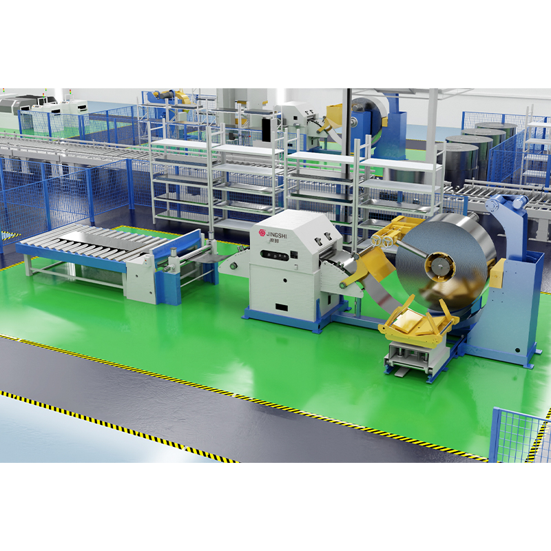 High Precision Decoiler Straightener Feeder & CTL Line Suppliers, Manufacturers,Suzhou JingShi Intelligent Equipment Co., Ltd is Custom High Precision Decoiler Straightener Feeder & CTL Line Manufacturers, High Precis...View Product →
What to Evaluate When Choosing a Steel Coil Machinery Supplier
The design and production of steel coil machinery varies significantly between suppliers, and the purchase decision should test more than the price list. Three checks are worth applying.
First, verify the design capability. Ask how the supplier calculates frame stiffness and roll deflection, whether finite element analysis is used for heavy sections, and how the hydraulic force is matched to the material envelope. A supplier that cannot explain the calculation method may be assembling a machine to a drawing without understanding its limits.
Second, confirm the manufacturing scope. In-house machining of frames and rolls gives the manufacturer direct control over the tolerances discussed earlier. If the frame is machined in one setup and roll grinding is done on machines the supplier owns, the consistency of the finished machine can be examined during the factory acceptance test.
Third, review the application engineering. Will the supplier confirm the machine configuration against your actual material list, including yield strength variations between steel suppliers? Engineers often use a decision matrix to compare leveler designs across material range, rigidity, and maintenance access; the seven-factor decision matrix for sheet metal leveler selection is a useful starting point.
The most common sourcing mistakes are not about the machine itself. Buying on roll count alone, ignoring yield strength, under-specifying maintenance access, and forgetting spare parts lead time all create problems that a well-documented design and testing process would have prevented. A machine is bought by name and price, but it is justified by flatness measurements, uptime, and the number of good parts produced per shift.